
Tensioning device of concrete centrifugal pile mold

A concrete and tensioning technology, applied in reinforcement molding, ceramic molding machines, manufacturing tools, etc., can solve the problems of inconvenient use and single function, and achieve the effect of convenient use and avoiding single function

Pending Publication Date: 2020-12-11
广东华岩建材有限公司 +1
View PDF0 Cites 0 Cited by
  • Summary
  • Abstract
  • Description
  • Claims
  • Application Information

AI Technical Summary

Problems solved by technology

The existing problem is: in the process of using the aforementioned structure, it is limited by the aforementioned structure, resulting in a single function and inconvenient use

Method used


Image

  • Tensioning device of concrete centrifugal pile mold
  • Tensioning device of concrete centrifugal pile mold
  • Tensioning device of concrete centrifugal pile mold

Examples


Embodiment Construction

[0024] The implementation of the present invention will be illustrated by specific specific examples below, and those skilled in the art can easily understand other advantages and effects of the present invention from the contents disclosed in this specification.

[0025] It should be noted that the structures, proportions, sizes, etc. shown in the drawings of this specification are only used to match the content disclosed in the specification, for those who are familiar with this technology to understand and read, and are not used to limit the conditions for the implementation of the present invention , so it has no technical substantive meaning, and any modification of structure, change of proportional relationship or adjustment of size shall still fall within the scope of the disclosure of the present invention without affecting the functions and objectives of the present invention. within the range covered by the technical content. At the same time, terms such as "upper", ...


PUM


Abstract

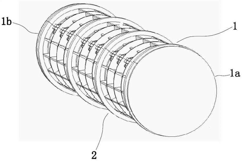
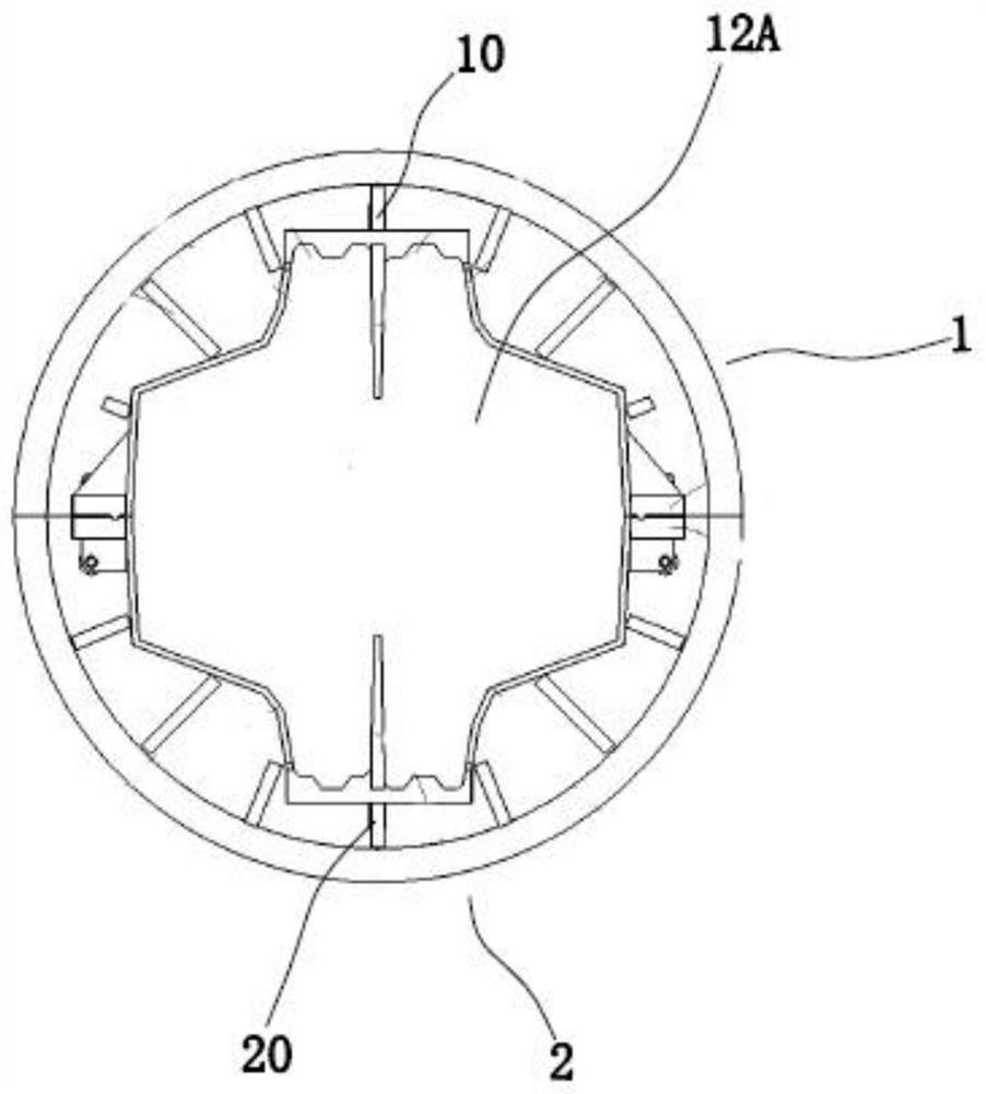
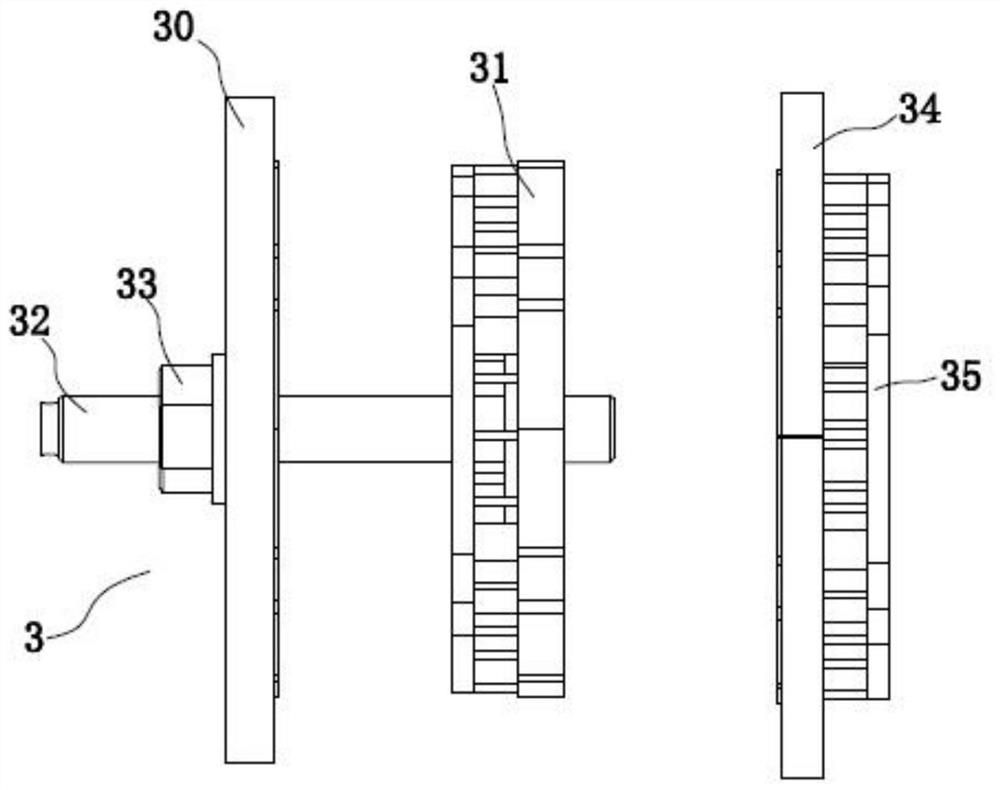
The invention provides a tensioning device of a concrete centrifugal pile mold. The tensioning device comprises a first mold body and a second mold body which are provided with inner cavities and areused for concrete and further comprises a tensioning device body; a screw sequentially penetrates through a nut, a supporting plate and a head tensioning device in the front-and-back direction and extends out of a mold cavity; the nut is screwed to the side wall of the screw and abuts against the surface, deviating from the head tensioning device, of the supporting plate in the axis direction, sothat one surface of the head tensioning device is closely attached to a front embedding groove of the mold cavity, and the other surface of the head tensioning device is embedded in an embedding hole;the end of the screw extending out of the mold cavity in the front-and-back direction is sequentially inserted into a tail tensioning device and a tail plate in a penetrating manner; an accommodatinggroove with a side opening is formed in the surface, facing the supporting plate, of the tail plate, and the tail tensioning device is embedded into the accommodating groove, so that the surface of the tail tensioning device is closely attached to a back embedding groove of the mold cavity. Compared with the prior art, the tensioning device has the advantages that the tensioning device body is arranged, the prestress tensioning function on the concrete centrifugal pile mold is achieved, the defect that the function is single is overcome, and the tensioning device is convenient to use.

Description

technical field [0001] The invention relates to a tensioner for a concrete centrifugal pile form. Background technique [0002] At present, retaining structures are required for revetments and dikes in river regulation, and concrete sheet piles are mostly used in existing retaining structures. In the prior art, there is a concrete centrifugal pile form, which includes a first mold and a second mold for concrete each having an inner cavity, the first partition is provided in the first mold, and the second mold has a A second partition is provided, and the first partition and the second partition divide the inner cavity into a mold cavity. The existing problem is: in the process of using the aforementioned structure, it is limited by the aforementioned structure, resulting in a single function and inconvenient use. [0003] For this reason, the invention provides a kind of tensioner of concrete centrifugal pile formwork. Contents of the invention [0004] In view of the a...

Claims


Application Information

Patent Timeline
Patent Type & Authority Applications(China)
IPC IPC(8): B28B21/62B28B21/30
CPCB28B21/30B28B21/62
Inventor 杨华耀
Owner 广东华岩建材有限公司
Learn More