
A grate tooth sealing device for reducing gap leakage flow

A technology of leakage flow and clearance, applied in the field of grate sealing devices, can solve the problems of increasing leakage, reducing engine life, and causing danger, and achieves the effect of improving the flow mixing effect, avoiding the increase of leakage flow, and reducing the leakage flow.

Active Publication Date: 2021-11-16
NANJING UNIV OF AERONAUTICS & ASTRONAUTICS
View PDF7 Cites 0 Cited by
  • Summary
  • Abstract
  • Description
  • Claims
  • Application Information

AI Technical Summary

Problems solved by technology

If the sealing gap is too large, the leakage will increase, which is not conducive to improving engine efficiency
However, if the gap is too small, the rotation of the rotor will cause the tooth tip and the stator bush to scratch, which will reduce the life of the engine and even cause danger.

Method used


Image

  • A grate tooth sealing device for reducing gap leakage flow
  • A grate tooth sealing device for reducing gap leakage flow
  • A grate tooth sealing device for reducing gap leakage flow

Examples


Embodiment Construction

[0023] The embodiments of the present invention will be described in further detail below with reference to the accompanying drawings.

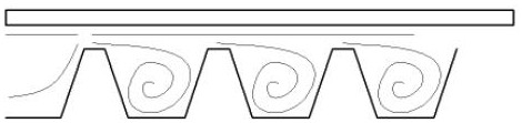
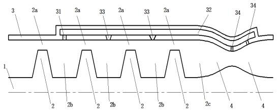
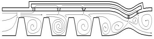
[0024] A grate sealing device for reducing gap leakage flow in this embodiment includes a built-in rotating part 1 . The rotating part 1 is provided with a plurality of axially arranged sealing grate teeth 2 , and the rotating part 1 is provided with external Sealing bushing 3, the outer peripheral surface of sealing grate teeth 2 and the inner annular surface of sealing bushing 3 are gap-fitted, so that a tooth tip gap 2a is formed between the tooth tips of sealing grate teeth 2 and the inner annular surface of sealing bushing 3 , a tooth cavity 2b is formed between the adjacent sealing grate teeth 2, the sealing bush 3 and the rotating part 1 cooperate at the tail to form a tapered and gradually expanded channel 4, and a transition section 2c is formed between the tapered and gradually expanded channel 4 and the grate teeth , wherein: the g...


PUM


Abstract

The invention discloses a grate tooth sealing device for reducing gap leakage flow. The grate tooth sealing device is provided with a drainage channel, and the sealing bush is provided with a drainage hole corresponding to the middle part of the first-stage tooth cavity. The drainage hole can The high-pressure gas in the first-stage tooth cavity is introduced into the drainage channel, and the sealing bush is provided with a first jet hole corresponding to the middle of each secondary tooth cavity, and the sealing bush is in the throat of the tapered and expanding channel. There is a second jet hole corresponding to the expansion section, the first jet hole and the second jet hole are connected with the drainage channel, the high-pressure airflow in the drainage channel can be injected from the first jet hole, and the fluid flowing out from the tooth tip gap is in the Strong mixing is formed in the tooth cavity, and the high-pressure airflow in the drainage channel can be ejected from the second jet hole, suppressing the main airflow in the tapering and expanding channel, and increasing the back pressure at the transition section. The invention has the technical effect of effectively reducing fluid leakage.

Description

technical field [0001] The invention relates to the technical field of aero-engines, in particular to a grate sealing device for reducing gap leakage flow. Background technique [0002] In rotating machinery such as aero-engines, due to a certain gap between the rotating rotor parts and the stator bushing, the gas leaks between the rotating and stationary parts. This leakage flow will cause the flow of the mainstream fluid to decrease, resulting in The efficiency of the engine is reduced, and even problems such as blade vibration and deformation will occur, affecting the performance and life of the engine. The grate seal is a non-contact dynamic seal structure with simple structure and reliable performance, which is used in rotating machinery such as aero-engines. It uses the special combined structure of the grate teeth and the sealing ring to consume the kinetic energy of the fluid, increase the flow resistance, and finally reduce the fluid leakage. [0003] With the imp...

Claims


Application Information

Patent Timeline
Patent Type & Authority Patents(China)
IPC IPC(8): F01D11/02F01D11/06F01D11/08F01D11/10
CPCF01D11/02F01D11/06F01D11/08F01D11/10
Inventor 王治国张勃陈远翔吉洪湖
Owner NANJING UNIV OF AERONAUTICS & ASTRONAUTICS
Learn More