Axial turbo engine with low gap losses

a technology of axial turbo engine and gap loss, which is applied in the direction of liquid fuel engine, vessel construction, marine propulsion, etc., can solve the problems of serious impairment of the overall efficiency of the rotor blade, and achieve the effect of reducing the leakage flow through the radial gap and reducing the leakage flow

Inactive Publication Date: 2011-08-04
SIEMENS ENERGY GLOBAL GMBH & CO KG
View PDF9 Cites 9 Cited by
  • Summary
  • Abstract
  • Description
  • Claims
  • Application Information

AI Technical Summary

Benefits of technology

[0019]Therefore, the radial projection and the radial recess are advantageously located in the region of the highest pressure load of the blade tip of the conventionally profiled rotor blade so that the leakage flow through the radial gap is reduced.
[0020]Furthermore, it is preferred that the curvature sections are formed in such a way that in the principal throughflow direction of the axial turbomachine the progression of the radial gap extends essentially in an edge-free and step-free manner. In this case, provision can be made for even more than four curvature sections both in the annulus inner side and at the blade airfoil tip in order to reduce the leakage flow through the radial gap.

Problems solved by technology

Brought about by this high pressure load, the leakage flow through the radial gap is particularly high so that as a result of the leakage flow the overall efficiency of the rotor blade is seriously impaired.

Method used


Image

  • Axial turbo engine with low gap losses
  • Axial turbo engine with low gap losses
  • Axial turbo engine with low gap losses

Examples


Embodiment Construction

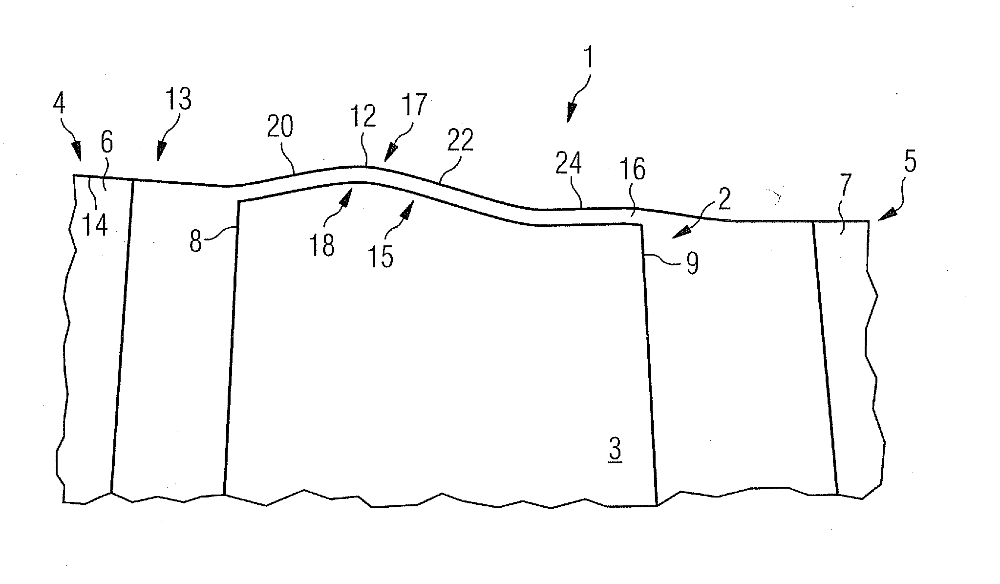
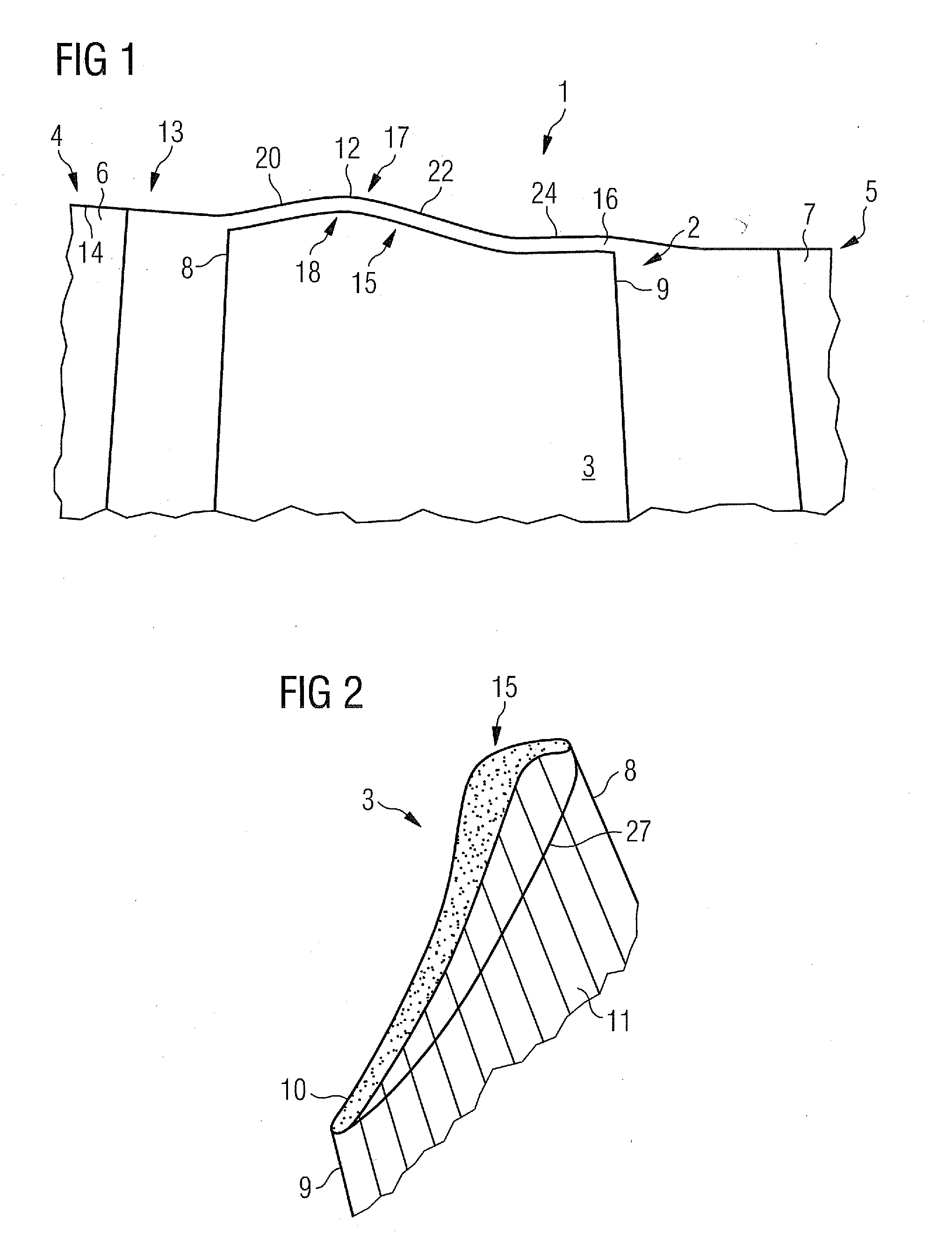
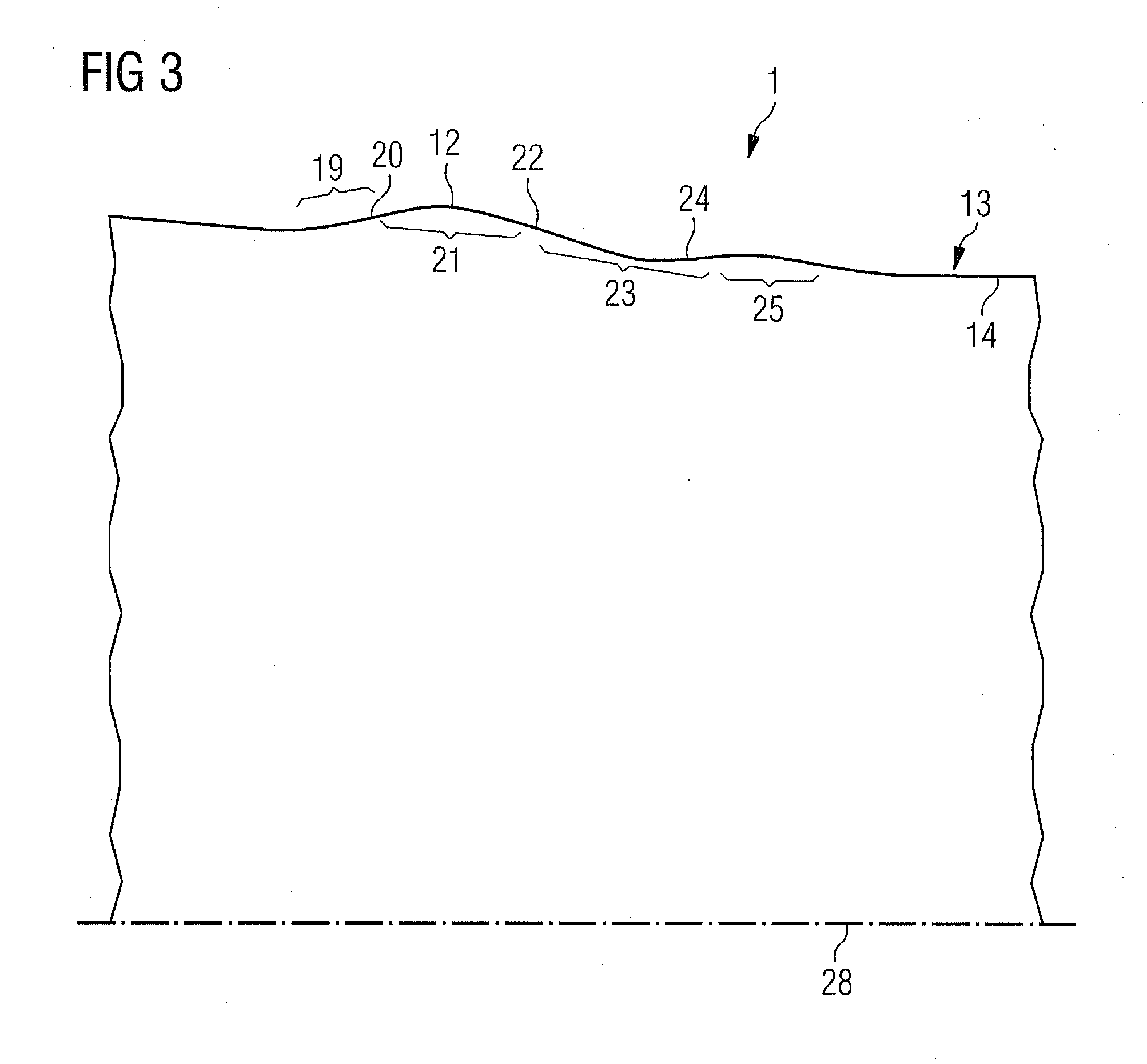
[0031]As is apparent from FIGS. 1 to 3, an axial compressor 1 has a rotor 2 which has a rotor blade cascade which is formed from a multiplicity of rotor blades 3. The axial compressor 1 is exposed to throughflow from left to right, as seen in FIGS. 1 and 3.

[0032]Furthermore, the axial compressor 1 has a first stator 4 upstream of the rotor blade 3 and a second stator 5 downstream of the rotor blade 3. The first stator 4 is formed from a multiplicity of first stator blades 6 and the second stator 5 is formed from a multiplicity of second stator blades 7.

[0033]The rotor blade 3 has a leading edge 8 on its end facing upstream and a trailing edge 9 on its end facing downstream, wherein the one side between the leading edge 8 and the trailing edge 9 is the pressure side 10 and the other side between the leading edge 8 and the trailing edge 9 is the suction side 11 of the rotor blade 3. A rectilinear profile chord, with a standard chord length of 100%, extends from the leading edge 8 to t...


PUM


Abstract

An axial turbomachine including a rotor blade cascade is provided. The rotor blade cascade includes rotor blades each including front edge, a radially outer free blade tip and an annular enclosure enclosing the rotor blade cascade with an annulus inner side by means of which the annular enclosure is arranged directly adjacent to the blade tips to give a radial gap between the enveloping ends of the blade tips and the annulus inner side. The rotor blades include a radial projection in the region of the front edge on the blade tip and the annular enclosure has an annular radial recess in the annulus inner side, arranged at a radial distance from the ends of the blade tips, such that in the main flow direction of the axial turbomachine the line of the radial projections on the side facing the radial gap matches the line of the radial recess.

Description

CROSS REFERENCE TO RELATED APPLICATIONS[0001]This application is the US National Stage of International Application No. PCT / EP2009 / 058681, filed Jul. 8 2009 and claims the benefit thereof. The International Application claims the benefits of European Patent Office application No. 08012959.6 EP filed Jul. 17, 2008. All of the applications are incorporated by reference herein in their entirety.FIELD OF INVENTION[0002]The invention refers to an axial turbomachine which has low tip clearance losses.BACKGROUND OF INVENTION[0003]An axial turbomachine has a casing and a rotor which is enclosed by the casing. The rotor has a hub contour which together with the inner contour of the casing forms a flow passage through the axial turbomachine. The rotor has a multiplicity of rotor stages which are formed in each case by a rotor blade cascade. The rotor blade cascades have a multiplicity of rotor blades which by one of their ends are fastened in each case on the rotor on the hub side and by thei...

Claims


Application Information

Patent Timeline
Patent Type & Authority Applications(United States)
IPC IPC(8): F01D5/22
CPCF01D5/143F01D5/145F01D5/20F05D2250/71Y02T50/671Y02T50/673F01D11/08Y02T50/60
Inventor AULICH, MARCELCORNELIUS, CHRISTIANKROGER, GEORG
Owner SIEMENS ENERGY GLOBAL GMBH & CO KG
Why Eureka
Try Eureka