Numerical control rotary table

A technology of rotary workbench and tabletop, which is applied in the direction of manufacturing tools, metal processing equipment, metal processing machinery parts, etc. It can solve the problems of large deformation of the workbench under pressure, difficulty in meeting precision machining, difficulty in guaranteeing service life, etc., and achieve stable operation High performance, guaranteed machining accuracy, and good axial accuracy

Pending Publication Date: 2022-04-29
江苏恒望机械科技有限公司
View PDF0 Cites 3 Cited by
  • Summary
  • Abstract
  • Description
  • Claims
  • Application Information

AI Technical Summary

Problems solved by technology

This is because with the increase of bearing capacity, the pressure deformation of the workbench will become larger and larger, and the running accuracy will be greatly reduced, making it difficult to meet the needs of precision machining.
Moreover, the pressure bearing capacity of the ultra-large rotary table will cause huge wear and tear during its operation, and the service life is difficult to guarantee

Method used


Image

  • Numerical control rotary table
  • Numerical control rotary table
  • Numerical control rotary table

Examples


Embodiment approach

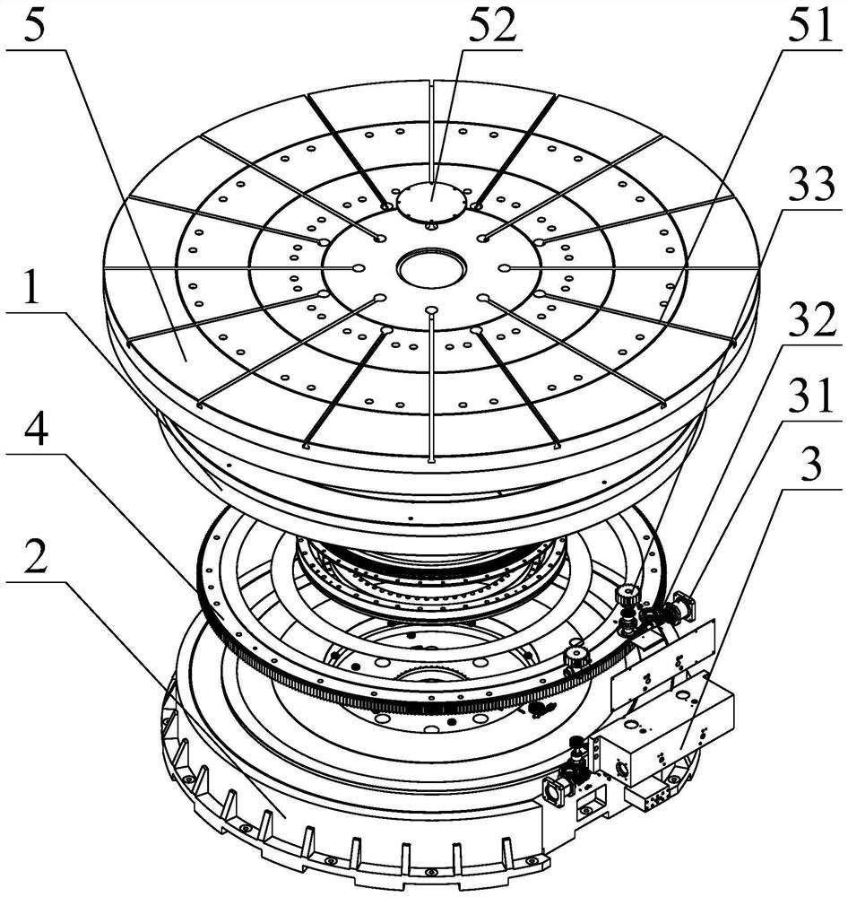
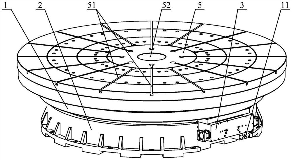
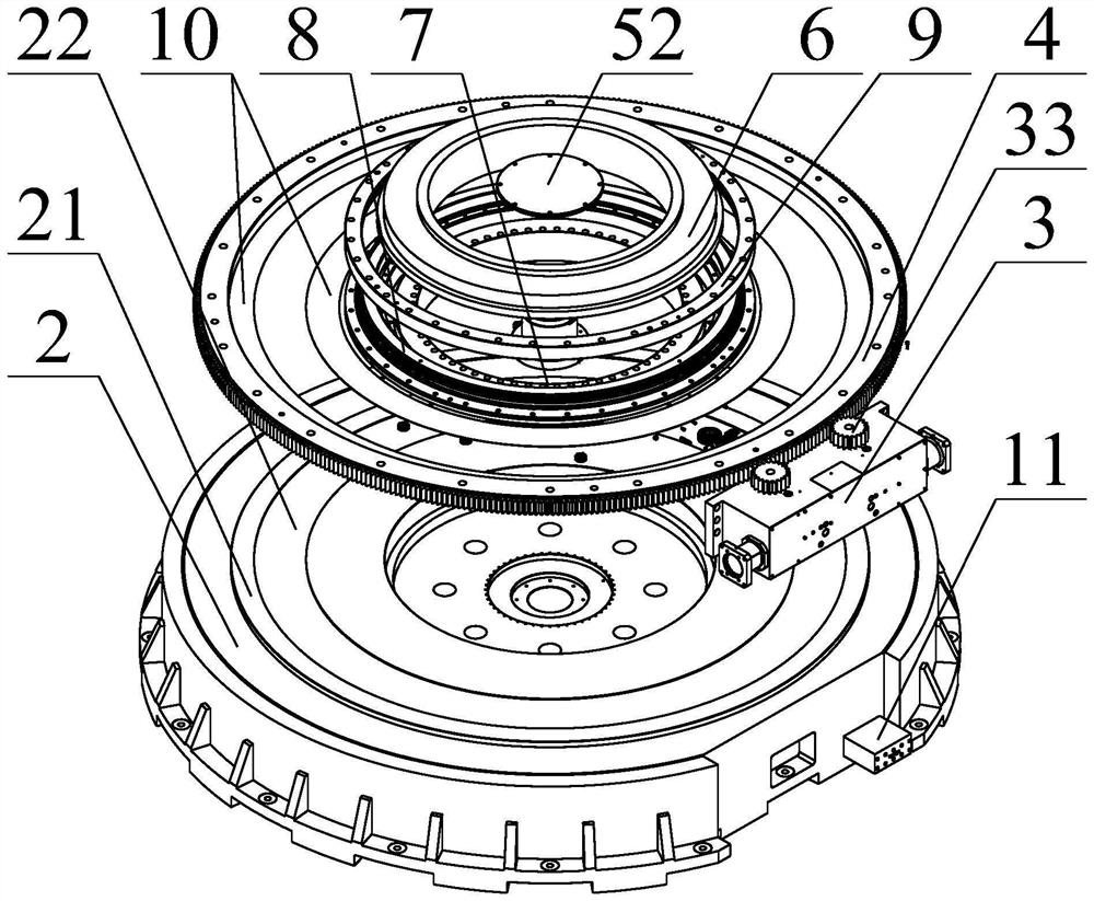
[0046] Such as Figure 1 to Figure 5 As shown, the present invention also has a second embodiment. The structure of this embodiment is basically similar to that of the first embodiment, and the difference lies in the addition of a sub-table 5 .

[0047] In this embodiment, a sub-table 5 is fixedly installed on the top of the table 1 .

[0048] The design of the sub-table 5 is mainly due to the load bearing considerations for large-sized workpieces. For large-sized workpieces, the smaller table top 1 is difficult to fix the workpiece stably, and the workpiece is easy to shake or shake during operation. After the auxiliary table 5 is used, the auxiliary table 5 can be designed according to the size of the workpiece to meet the needs of fixing.

[0049] Instead of directly adopting a large-sized table top 1, it is entirely out of consideration of stable operation and bearing capacity. With a large-sized table top 1, the bearing capacity distribution is too complicated, and it i...

experiment example

[0056] The force analysis is carried out on the rotary table designed in the first embodiment of the present invention to detect whether the design of the present invention can meet the bearing requirements.

[0057] Apply a force of 400,000N (40t) within the range of diameter 2293mm to 3800mm on the table surface, and conduct finite element simulation analysis on the strength of the table. The analysis results are shown in Figure 7 .

[0058] Depend on Figure 7 It can be seen from the displayed analysis results that the maximum deformation of the table 1 of the rotary table of the present invention occurs at the outermost edge of the table 1, and the maximum deformation is 0.027mm, which is extremely small and belongs to elastic deformation, and its influence on welding and the use of the turntable can be ignored .

[0059] It can be seen from the results of the experimental example that the present invention can meet the requirement of high-precision load bearing of 40 t...


PUM


Abstract

The invention relates to a numerical control rotating table which comprises a table top, a base and a driving mechanism fixedly installed on the base, a circular assembling groove is formed in the top of the base, an annular guide rail is arranged on the inner side edge of the assembling groove, a driving gear ring is fixedly installed at the bottom of the table top, and the driving gear ring is connected with the base in a matched mode through a thrust roller bearing; a disc shaft is fixedly connected to the bottom of the center of the table top and connected with the base in a matched mode through a double-row cylindrical roller bearing. An air floatation groove is formed in the area, between the disc shaft and the driving gear ring, of the base and used for supporting the radial middle area of the table top through air floatation, and an air cavity matched with the air floatation groove is formed in the position, corresponding to the air floatation groove, of the bottom of the table top; the driving mechanism adopts a double-lead worm gear pair; the numerical control rotary table further comprises a brake mechanism. Through the special structural design, the bearing capacity of 35 tons or above can be achieved, the operation precision is extremely high, operation is very stable, and the service life is long.

Description

technical field [0001] The invention relates to the technical field of mechanical processing equipment, in particular to a numerically controlled rotary worktable. Background technique [0002] In order to cope with the increasing processing of complex parts and improve processing accuracy and efficiency, multi-axis machine tools (5 axes or above) and compound machine tools have become the main equipment for precision machining. The CNC rotary table is not only the CNC rotary shaft of the equipment, but also plays the role of bearing the weight of the workpiece and clamping the workpiece, which has extremely high requirements for its precision and bearing capacity. There are two functions of the CNC rotary table, one is feed indexing, that is, when the workpiece is not cutting, the workpiece is indexed and rotated or positioned at any index within the range of 360°; the other is to realize the feed in the circumferential direction of the worktable Movement, that is, when cu...

Claims


Application Information

Patent Timeline
Patent Type & Authority Applications(China)
IPC IPC(8): B23Q1/50B23Q5/20
CPCB23Q1/50B23Q5/20
Inventor 李光荣魏泽华
Owner 江苏恒望机械科技有限公司
Why Eureka
Try Eureka