Gas turbine

a technology of gas turbines and turbine blades, applied in the direction of machines/engines, stators, liquid fuel engines, etc., can solve the problems of high thermal load, considerable efficiency loss, and high thermal load on components and parts subject to these temperatures, so as to reduce flow losses, reduce radial gaps, and high efficiency

Inactive Publication Date: 2015-07-07
SIEMENS AG
View PDF18 Cites 2 Cited by
  • Summary
  • Abstract
  • Description
  • Claims
  • Application Information

AI Technical Summary

Benefits of technology

[0013]The annular segments which form the outer wall of the hot gas path in the axial section of the rotor blades are in this case normally hooked into the stator blade support via hook elements. Since the stator blade support is a relatively massive component which is subject to comparatively severe deformation during operation, the cross-sectional contour which is formed by all the annular segments in the operating state is frequently governed by the attachment or bracing of the annular segments in the stator blade support, and its deformation during operation. It is therefore not absolutely essential for the cold contour of the outer wall, which consists of annular segments, to be manufactured itself in an elliptical shape, since the definition which is forced by the contact points on the hook elements occurs in any case. The compensation for the ovality of the stator blade support can therefore be achieved by advantageously matching only the individual hook elements of the annular segments such that the outer wall has an essentially elliptical cross-sectional contour. Since these annular segments are replaceable maintenance parts, this on the one hand makes it possible to retrofit existing gas turbines while on the other hand making it possible to compensate for manufacturing errors in stator blade supports and, furthermore, allowing particularly simple matching to different methods of operation, including modified other measures to reduce the radial gaps.
[0014]In one advantageous refinement, during the production of the hollow-conical or hollow-cylindrical components of the gas turbine, the lengths of the main and secondary axes of the elliptical cross-sectional contour are in each case chosen such that the respective component has an essentially circular cross-sectional contour after the thermal deformation which occurs in the operating state. This can be done, for example, by introduction of ovality offset through 90 degrees with respect to that expected during operation. The elliptical shape of these components is therefore chosen such that the deformations in the operating state are compensated for precisely, such that this results in a circular cross section during operation, and therefore in the same radial gaps over the entire circumference of the gas turbine, that is to say the radial gaps no longer vary over the circumference. Even during the design phase, this therefore allows the radial gaps to be designed to be correspondingly narrow, resulting in higher efficiency of the gas turbine.
[0016]The explained elliptical configuration of the hollow-conical or hollow-cylindrical components of the gas turbine when not in operation makes it possible to achieve an essentially circular shape for the operating state and, furthermore, the elliptical shape which now exists when not in operation can be taken into account further in the design of the radial gaps and the design of the gas turbine. This problem can be overcome by a gas turbine which is equipped with the described components that have been manufactured with an opposing angle design having a bearing device for the turbine shaft, which is designed such that the turbine shaft can be moved along the turbine axis. This allows the turbine shaft to be moved in the hot gas flow direction in the cold operating state, thus resulting in the radial gaps being enlarged when the outer wall has a hollow-conical shape, with an enlargement of the radius in the direction of the hot gas flow when cold and not in operation, as a result of which the opposing ovality which is still present in the cold state (for example when starting up the gas turbine) does not represent any restriction to the radial gaps which can be achieved in the hot state. This makes it possible to achieve even higher efficiency from the gas turbine.
[0018]The advantages achieved by the invention are, in particular, that deliberately designing the hollow-conical or hollow-cylindrical components of a gas turbine such that they have an essentially elliptical cross-sectional contour when not in operation, allows the gas turbine to have a particularly high efficiency, by reducing the radial gaps. The previous elliptical deformation, for example of the outer wall of the annular hot gas channel or the inner wall of the stator blade support during operation, is reduced or avoided by elliptical manufacture, in which the ovality which is incorporated in the cold state is rotated through 90° with respect to the ovality which occurs during operation. Unifying the radial gaps on the circumference reduces the flow losses and therefore improves the machine efficiency. In addition, the cold gaps when in the new state can be reduced, since the amount of the ovality need no longer be kept available for gap generation.

Problems solved by technology

However, when the working medium is at high temperatures such as these, the components and parts which are subject to these temperatures are subject to high thermal loads.
However, a correspondingly comparatively generous design of the radial gaps leads to considerable efficiency losses.

Method used


Image

  • Gas turbine
  • Gas turbine
  • Gas turbine

Examples


Embodiment Construction

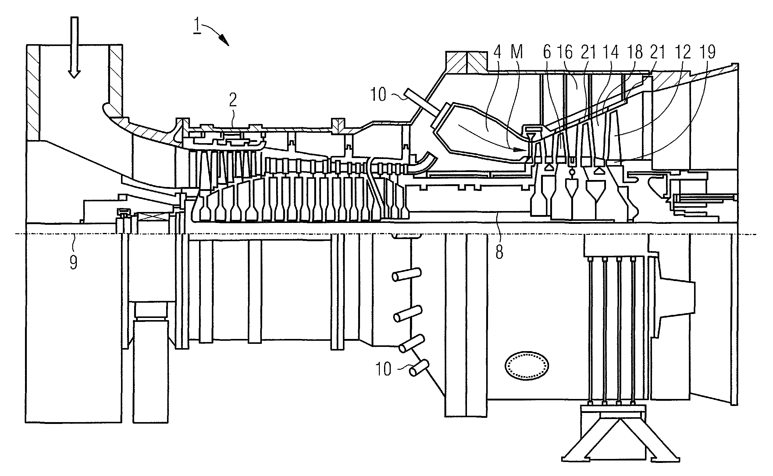
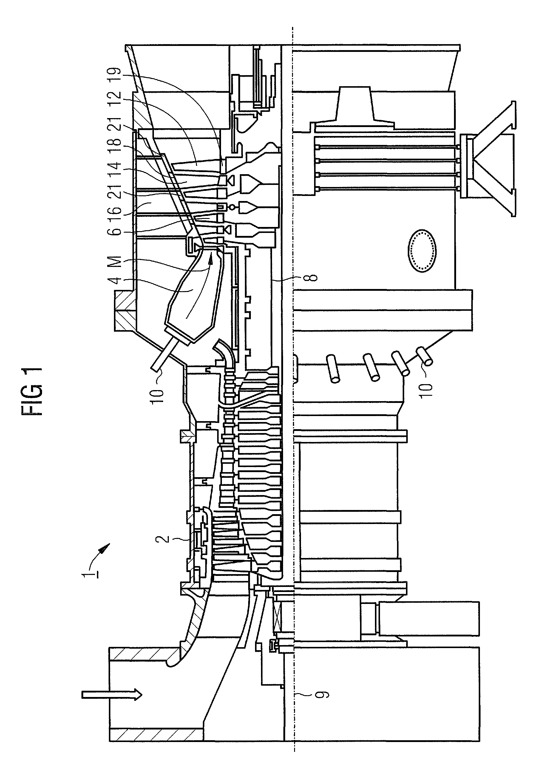
[0024]The gas turbine 1 as shown in FIG. 1 has a compressor 2 for combustion air, a combustion chamber 4 and a turbine unit 6 for driving the compressor 2, and for driving a generator, which is not illustrated, or a working machine. For this purpose, the turbine unit 6 and the compressor 2 are arranged on a common turbine shaft 8, which is also referred to as the turbine rotor, to which the generator and / or the working machine are / is also connected, and which is mounted such that it can rotate about its turbine axis 9. The combustion chamber 4, which is in the form of an annular combustion chamber, is fitted with a number of burners 10 for combustion of a liquid or gaseous fuel.

[0025]The turbine unit 6 has a number of rotor blades 12 which can rotate and are connected to the turbine shaft 8. The rotor blades 12 are arranged in the faun of a ring on the turbine shaft 8 and therefore foam a number of rotor blade rows. Furthermore, the turbine unit 6 comprises a number of stationary st...


PUM


Abstract

A gas turbine including a plurality of hook elements disposed one inside the other and designed substantially in the form of hollow cones or hollow cylinders, and including a stator blade support, is intended to enable an especially high efficiency while maintaining the greatest possible operating safety and operating life. To this end, at least one of the hook elements or the stator blade support has a substantially elliptical cross-sectional contour.

Description

CROSS REFERENCE TO RELATED APPLICATIONS[0001]This application is the US National Stage of International Application No. PCT / EP2009 / 061936, filed Sep. 15, 2009 and claims the benefit thereof. The International Application claims the benefits of European Patent Office application No. 08020190.8 EP filed Nov. 19, 2008. All of the applications are incorporated by reference herein in their entirety.FIELD OF INVENTION[0002]The invention relates to a gas turbine having a stator blade support, which is essentially hollow-conical or hollow-cylindrical and extends along a machine axis, and having an outer wall, which is essentially hollow-conical or hollow-cylindrical and is segmented into annular segments in the circumferential and / or axial direction, of an annular hot gas path, whose annular segments are attached by means of a number of hook elements to the inside of the stator blade support.BACKGROUND OF INVENTION[0003]Gas turbines are used in many fields, for driving generators or working...

Claims


Application Information

Patent Timeline
Patent Type & Authority Patents(United States)
IPC IPC(8): F01D25/24F01D25/26
CPCF01D25/246F01D25/26
Inventor BENKLER, FRANCOISBUCHAL, TOBIASBOTTCHER, ANDREASHARTMANN, MARTINHULSMEIER, PATRICIAKAHLSTORF, UWEMALDFELD, EKKEHARDMINNINGER, DIETERNEUBAUER, MICHAELSCHRODER, PETERTETERUK, ROSTISLAVVEITSMAN, VYACHESLAV
Owner SIEMENS AG
Why Eureka
Try Eureka