Turbine

a turbine and engine technology, applied in the field of turbines, can solve problems such as leakage of steam through, and achieve the effect of reducing leakage flow ra

Active Publication Date: 2012-12-20
MITSUBISHI HEAVY IND LTD
View PDF24 Cites 9 Cited by
  • Summary
  • Abstract
  • Description
  • Claims
  • Application Information

AI Technical Summary

Benefits of technology

[0024]According to the present invention, the first main vortex that flows from the tip end of the upstream end side seal fin toward the bottom surface of the annular groove is formed. Therefore, the fluid passing through the small gap formed between the tip end of the seal fin and the bottom surface of the annular groove is contracted due to the first main vortex, so that the leakage flow rate is reduced.

Problems solved by technology

However, leakage steam passing through the gap at the tip end portion of the rotating blade to the downstream side does not impart rotational force to the rotating blade.
In addition, leakage steam passing through the gap at the tip end portion of the stationary blade on the downstream side is not used by the stationary blade to convert pressure energy into velocity energy.

Method used


Image

  • Turbine
  • Turbine
  • Turbine

Examples


first embodiment (

First Embodiment(Steam Turbine)

[0035]Next, a steam turbine according to a first embodiment of the present invention will be described on the basis of FIGS. 1 to 5.

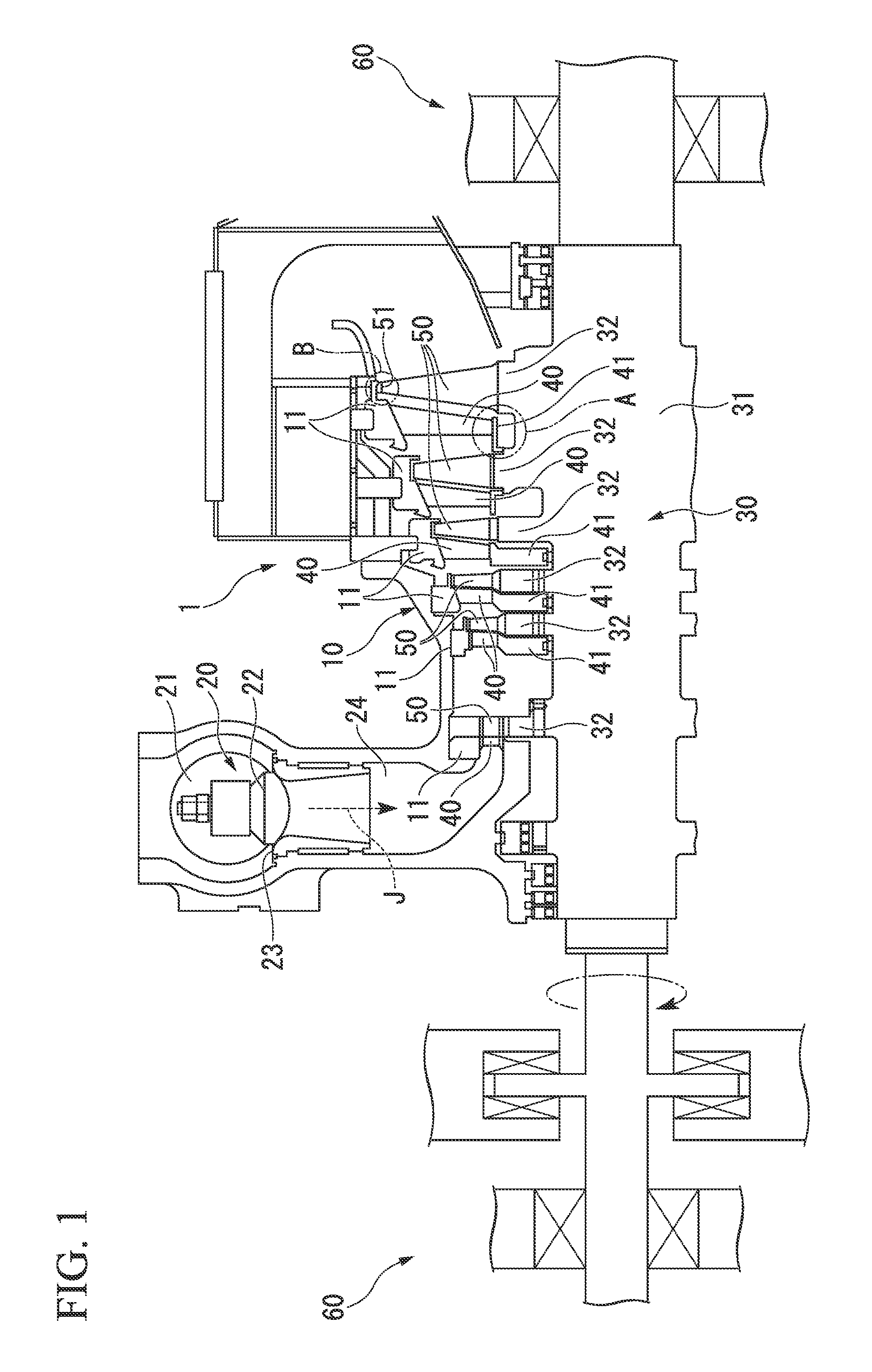
[0036]FIG. 1 is a cross-sectional view illustrating the schematic configuration of the steam turbine 1 according to the first embodiment of the present invention.

[0037]The steam turbine 1 includes: a casing 10; regulating valves 20 that regulate the amount and pressure of the steam J that flows into the casing 10; a shaft body (rotor) 30 rotatably provided inside the casing 10 to transmit power to a machine such as a power generator (not shown); stationary blades 40 held in the casing 10; rotating blades 50 provided to the shaft body 30; and a bearing unit 60 that supports the shaft body 30 so as to be rotatable about the axis.

[0038]The casing 10 has an internal space that is airtightly sealed and is a flow path of the steam J. To the inner wall surface of the casing 10, ring-like partition plate outer races 11 into which ...

second embodiment

[0075]Next, a second embodiment of the present invention will be described on the basis of FIGS. 6 and 7 with reference to FIG. 1. In addition, like elements which are the same as those of the first embodiment are denoted by like reference numerals (the same applies to the following embodiments).

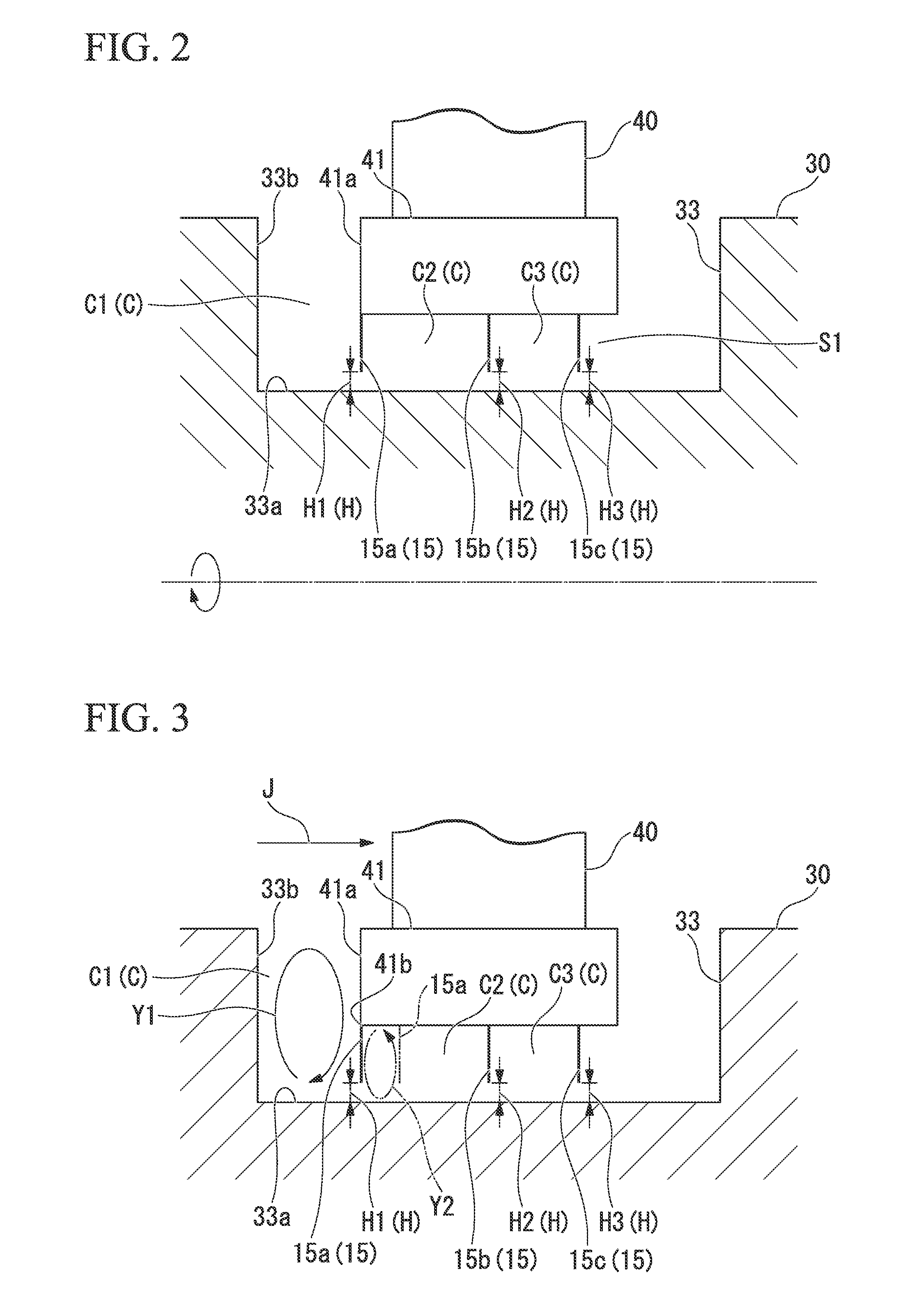
[0076]FIG. 6 is an explanatory view for explaining the second embodiment and corresponds to FIG. 2 (the enlarged view of the portion A of FIG. 1).

[0077]In the second embodiment of the present invention, the basic configurations in which the steam turbine 1 includes the casing 10, the regulating valve 20 that regulates the amount and pressure of the steam J that flows into the casing 10, the shaft body (rotor) 30 rotatably provided inside the casing 10 to transmit power to the machine such as a power generator (not shown), the stationary blades 40 held in the casing 10, the rotating blades 50 provided to the shaft body 30, and the bearing unit 60 that supports the shaft body 30 so as to be ro...

third embodiment

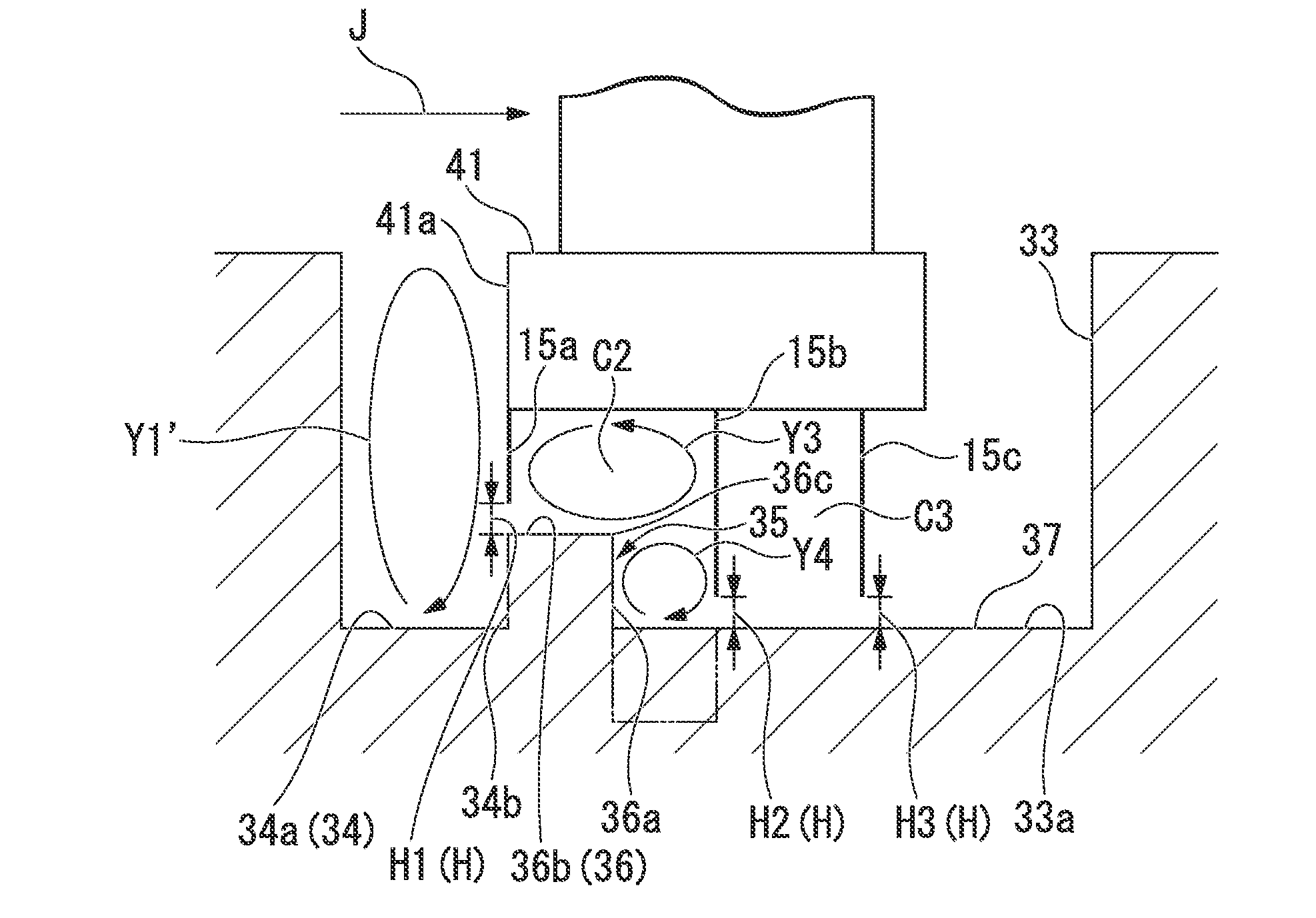
[0091]Next, a third embodiment of the present invention will be described on the basis of FIG. 8.

[0092]FIG. 8 is an explanatory view for explaining the third embodiment and corresponds to FIG. 2 (the enlarged view of the portion A of FIG. 1). Here, the third embodiment is different from the second embodiment in that a stepped portion 35 is provided in the annular groove 33 of the third embodiment in addition to the small annular groove 34 whereas the small annular groove 34 is formed at the site corresponding to the first cavity Cl in the annular groove 33 of the second embodiment.

[0093]The stepped portion 35 has a projecting portion 36 projecting at a position of the bottom surface 33a of the annular groove 33 corresponding to the second cavity C2 toward the upstream side, that is, to be close to the first seal fin 15a. Due to the projecting portion 36, the height of the bottom surface 33a of the annular groove 33 is reduced by a stage toward the downstream side from the end surfac...


PUM


Abstract

Provided is a turbine in which seal fins (15) are provided to a hub shroud (41) to protrude toward a bottom surface (33a) of an annular groove (33), small gaps (H) are formed between the tip ends of the seal fins and the bottom surface of the annular groove, and assuming that the axial distance between a first seal fin (15a) disposed on the front edge side of the hub shroud among the seal fins and a front edge (41a) of the hub shroud is (L) and the axial distance between the front edge of the hub shroud and an inside surface (33b) of the annular groove is (Bu), the first seal fin is disposed to satisfy L/Bu<0.3.

Description

TECHNICAL FIELD[0001]The present invention relates to a turbine used in, for example, a power plant, a chemical plant, a gas plant, an ironworks, a ship, or the like.[0002]Priority is claimed on Japanese Patent Application No. 2010-040920, filed on Feb. 25, 2010, the content of which is incorporated herein by reference.BACKGROUND ART[0003]Hitherto, as a type of steam turbine, a steam turbine which includes a plurality of stages each of which has a casing, a shaft body (rotor) rotatably provided inside the casing, stationary blades arranged to be fixed to the inner peripheral portion of the casing, and rotating blades provided in the radial forms to a shaft body on the downstream side of the stationary blades, has been known. Among such steam turbines, in the case of an impulse turbine, the pressure energy of the steam is converted into the velocity energy by the stationary blades, and the velocity energy is converted into rotational energy (mechanical energy) by the rotating blades....

Claims


Application Information

Patent Timeline
Patent Type & Authority Applications(United States)
IPC IPC(8): F01D11/08
CPCF01D11/08F05D2240/55F16J15/447F05D2220/31F05D2240/127F01D11/001F01D11/02
Inventor MATSUMOTO, KAZUYUKIKUWAMURA, YOSHIHIROYAMA, HIROHARUTANAKA, YOSHINORIMATSUO, ASAHARU
Owner MITSUBISHI HEAVY IND LTD
Why Eureka
Try Eureka