Pump-Controlled Hydraulic Circuits for Operating a Differential Hydraulic Actuator

a hydraulic circuit and differential actuator technology, applied in the direction of fluid-pressure actuators, telemotors, servomotors, etc., can solve the problems of throttling losses, energy losses, and throttling losses still representing 35% of the energy received

Active Publication Date: 2018-09-20
UNIVERSITY OF MANITOBA
View PDF8 Cites 10 Cited by
  • Summary
  • Abstract
  • Description
  • Claims
  • Application Information

AI Technical Summary

Benefits of technology

[0062]first and second main fluid lines respectively connecting first and second sides of the reversible hydraulic pump to extension and retraction sides of the differential hydraulic actuator; a hydraulic charging system for supplying / releasing charging fluid to and from the first and second main fluid lines to compensate for differential flow on opposing sides of the differential hydraulic actuator; first and second charging lines respectively connecting the charging circuit to the first and second main fluid lines; and at least one valve operably installed in the first and / or second charging lines and operable to switch between at least a first charging fluid supply / release state enabling flow through the first circuit-charging line between the first main fluid line and the charging circuit and a second charging fluid supply / release state enabling flow through the second circuit-charging line between the second main fluid line and the charging circuit; said method comprising running the hydraulic circuit in a throttled mode in a critical loading zone of the four-quadrant mode of operation, and running the hydraulic circuit in an unthrottled mode outside the critical loading zone, whereby the throttled mode provides vibration dampening in the critical loading zone, while throttling energy losses are avoided outside the shifted critical loading zone.
[0064]According to a fourth aspect of the invention, there is provided a method of controlling operation of a differential hydraulic actuator via a hydraulic circuit comprising a reversible hydraulic pump cooperating with a differential hydraulic cylinder to provide a four quadrant operation including a first load-resistive actuator-extension quadrant, a second load-assistive actuator-extension quadrant, a third load-resistive actuator-retraction quadrant and a fourth load-assistive actuator-retraction quadrant; first and second main fluid lines respectively connecting first and second sides of the reversible hydraulic pump to extension and retraction sides of the differential hydraulic actuator; a hydraulic charging system for supplying / releasing charging fluid to and from the first and second main fluid lines to compensate for differential flow on opposing sides of the differential hydraulic actuator; first and second charging lines respectively connecting the charging circuit to the first and second main fluid lines; and at least one valve operably installed in the first and / or second charging lines and operable to switch between at least a first charging fluid supply / release state enabling flow through the first circuit-charging line between the first main fluid line and the charging circuit and a second charging fluid supply / release state enabling flow through the second circuit-charging line between the second main fluid line and the charging circuit; said method comprising shifting a critical loading zone in the fourth load-assisted actuator-extension quadrant of the four quadrant operation to a lower loading range, whereby vibration amplitude in the critical loading zone is reduced due to lower loading values in the lower loading range of the shifted critical loading zone.
[0065]The method may comprise running the hydraulic circuit in a throttled mode in the shifted critical loading zone, and running the hydraulic circuit in an unthrottled mode outside the shifted critical loading zone, whereby the throttled mode provides vibration dampening in the shifted critical loading zone, while throttling energy losses are avoided outside the shifted critical loading zone.
[0078]wherein the default position of the spool places the first and second outer flow obstructing portions of the spool in positions substantially, but not fully, obstructing the first and second connection ports and placing the first and second flow-enabling sections at the third and fourth connection ports to enable the leakage flow from the first connection port to the third connection port and from the second connection port to the fourth connection port, the first input is operable under sufficient fluid pressure to drive the displaceable member toward the first operating position in the first direction to increase the opening of the second connection port while maintaining an open state of the fourth connection port and reducing the leakage flow between the first and third connection ports before fully closing off said leakage flow between the first and third connection ports as the second connection port continues opening to enable free flow between the second and fourth connection ports in the first operating position, and the second input is operable under sufficient fluid pressure to drive the displaceable member toward the second operating position in the second direction to increase the opening of the first connection port while maintaining an open state of the third connection port and reducing the leakage flow between the second and fourth connection ports before fully closing off said leakage flow between the second and fourth connection ports as the first connection port continues opening to enable free flow between the first and third connection ports in the second operating position.

Problems solved by technology

Throttling losses in valves represent one of the main energy losses in hydraulic circuits presently used in these machines.
Nevertheless, throttling losses still represent 35% of the energy received by a hydraulic system equipped with load-sensing technology in a typical excavating machine [5].
[12] further showed that the circuit with two pilot operated check valves (POCVs) is unstable at low loading operations.
This approach, however, requires additional control effort and extra sensors that increases system cost and complexity.
Also their experimental work was limited to low loading conditions and lacked the effect of mass inertia.
Nevertheless, these designs cannot regenerate energy [24].
From the above discussion it is seen that in spite of the large amount of studies on the topic, the use of throttle-less actuation technology for single rod cylinders has not been fully explored, compared to valve-controlled actuation, in terms of dynamic performance [19,25].
Otherwise, poor responses may be experienced in certain regions of operation, as outlined below.
However, interference in operation is expected when the two activating pressures p1 and p2 are close to each other [12].
This undesirable interference shows up in three ways: either both valves are closed or both are open or they alternatively open and close.
These conditions result in low performance [20].
However, in the motoring mode, the external load works to create this cracking pressure.
In this case, charge pump supplies both sides of the circuit with hydraulic flow and the actuator velocity is not fully controllable.

Method used


Image

  • Pump-Controlled Hydraulic Circuits for Operating a Differential Hydraulic Actuator
  • Pump-Controlled Hydraulic Circuits for Operating a Differential Hydraulic Actuator
  • Pump-Controlled Hydraulic Circuits for Operating a Differential Hydraulic Actuator

Examples


first embodiment

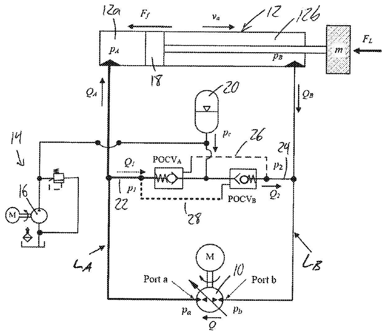
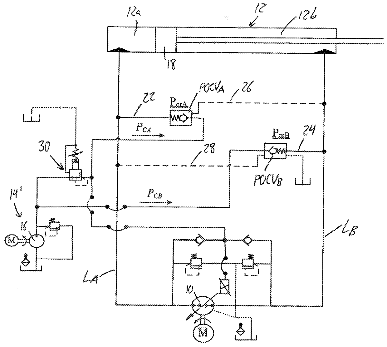
[0117]FIG. 4 illustrates a first embodiment hydraulic circuit of the present invention that, like the prior art circuit of FIG. 1, features the same layout of a reversible hydraulic pump 10, a single-rod differential linear actuator 12, and first and second main fluid lines LA, LB respectively connecting the first and second sides of the reversible pump 10 to the extension and retraction sides 12a, 12b of the actuator, and likewise includes first and second pilot-operated check valves POCVA, POCVB respectively installed on first and second charging lines 22, 24 that connect the first and second main fluid lines LA, LB to a charging system 14′ with a unidirectional pump 16. Once again, the POCVs are operated by way of cross pilot lines 26, 28 each connecting the pilot port of the respective POCV to the opposing main fluid line, whereby the differential flow to and from the cylinder in all four quadrants is accommodated in the same manner described for the prior art in the preceding b...

second embodiment

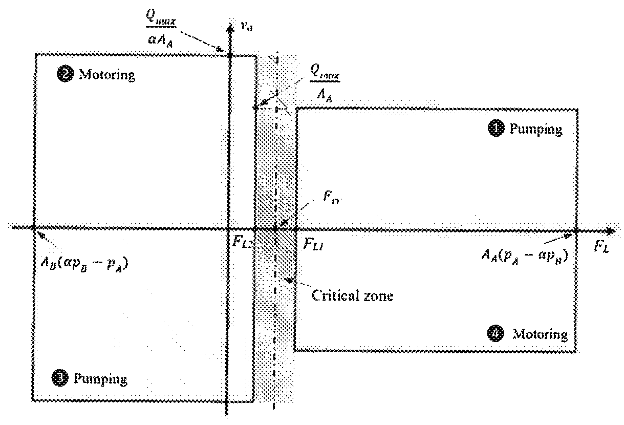
[0119]FIG. 5 shows a second embodiment which likewise performs shifting of the critical zones to lower ranges on the load force axis of the four quadrant operational plot, but instead of using two different respective charging pressures to uniquely characterize the two different actuating inputs respectively acting on the two POVCs, the circuit instead employs a singular 3-way 3-position double-piloted shuttle valve 32 that relies on a conventional single-pressure charging system 14 and is driven by two unique pilot inputs 32a, 32b from the two main lines LA and LB. The purpose of the charge system's unilateral low pressure pump, low pressure relief valve and tank / reservoir is feeding or releasing flow from each of the main lines as the operation requirements. In quadrants 1 and 2 the charge pump 16 of the charging system feeds the line LB and LA to balance the flow to the main pump and actuator respectively. In quadrants 3 and 4, the relief valve in the charging system allows the r...

third embodiment

[0123]FIG. 6 shows a third embodiment hydraulic circuit again using a singular shuttle valve 32′ having two pilot inputs 32a, 32b for driving the valve in opposing directions out of a default center position against the resistance of respective springs 34a, 34b, and using different piston areas and / or resistive spring constants for the two inputs. Like in FIG. 5, the first and second pilot inputs 32a, 32b are respectively fed by first and second pilot paths 36a, 36b coming off the first and second charging lines 22, 24. However, instead of using the conventional single-pressure charging system 14 of FIG. 5, the circuit instead uses the dual-pressure charging system 14′ of FIG. 4, with a lower charging pressure provided from the pressure reducing valve 30 than directly from the charge pump 16. Accordingly, the shuttle valve 32′ in this embodiment is a 4-way 3-position shuttle valve. In the default center position, the valve 32′ provides a throttled connection of first charging line 2...


PUM


Abstract

Pump-controlled hydraulic circuits are more efficient than valve-controlled circuits, as they eliminate the energy losses due to flow throttling in valves and require less cooling effort. Presently existing pump-controlled solutions for single rod cylinders encounter an undesirable performance during certain operating conditions. Novel circuit designs employ use of different charge pressures on a pair of pilot-operated charging-control valves or different piston areas and / or spring constants on a shuttle-type charging control valve to shift a critical loading region in a load-force / actuator-velocity plane to a lower load force range, thereby reducing the undesired oscillations experienced in the response of the typical critical loading region. One or more specialized valves are controlled by fluid pressures to provide throttling in the circuit only within the critical loading region, thereby reducing the oscillatory amplitude while avoiding throttling-based energy losses outside the critical region over the majority of the circuit's operational overall operating area.

Description

CROSS-REFERENCE TO RELATED APPLICATIONS[0001]This application claims benefit of U.S. Provisional App. No. 62 / 423,286, filed Nov. 17, 2016, the entirety of which is incorporated herein by reference.FIELD OF THE INVENTION[0002]The present invention relates generally to hydraulic circuits for controlling a differential actuator, and more particularly to pump-based control of such hydraulic circuits.BACKGROUND[0003]It has been seen that pump-controlled hydraulic circuits have better efficiency compared to valve-controlled circuits. Cleasby and Plummer [1] reported that their pump-controlled circuit consumed only 11% of energy required by a valve-controlled circuit to perform the same task. On the other hand, valve-controlled circuits, to date, exhibit better dynamic performance [2]. However, machine efficiency is becoming a real concern from economic and environmental points of view, especially in mobile hydraulic industry. Throttling losses in valves represent one of the main energy lo...

Claims


Application Information

Patent Timeline
Patent Type & Authority Applications(United States)
IPC IPC(8): F15B11/16
CPCF15B11/165F15B2211/355F15B2211/20553F15B2211/8613F15B2211/40576F15B2211/40507F15B7/006F15B21/14F15B2211/20561F15B2211/20569F15B2211/27F15B2211/30515F15B2211/5059F15B2211/613F15B2211/625F15B2211/6658F15B2211/7053F15B2211/761F15B2211/785F15B2211/8616F15B2211/88F15B7/10
Inventor IMAM, AHMED A.SEPEHRI, NARIMAN
Owner UNIVERSITY OF MANITOBA
Why Eureka
Try Eureka