
Power supply degradation determination apparatus

a technology of degradation determination and power supply, which is applied in the direction of electric/magnetic computing, analogue processes for specific applications, instruments, etc., can solve the problems of degradation of batteries too early, reducing the regenerative energy that can be recovered, and preventing degraded batteries from being degraded, so as to prolong the time required for terminal voltage stabilization, the effect of increasing the internal resistance of batteries

Active Publication Date: 2013-10-31
HONDA MOTOR CO LTD
View PDF8 Cites 20 Cited by
  • Summary
  • Abstract
  • Description
  • Claims
  • Application Information

AI Technical Summary

Benefits of technology

The invention aims to provide a device that can accurately determine the degradation of a power supply while reducing energy loss. This device can ensure the supply of power to an electric load during a desired idle stop time, while also providing power for starting the engine when it is stopped.

Problems solved by technology

For this reason, for example, when the apparatus is mounted to a vehicle capable of recovering regenerative energy, regenerative energy capable of being recovered is reduced by interrupting charging, and thus a problem of a drop in the fuel efficiency of a vehicle occurs.
Thereby, the internal resistance is easily detected as a higher value than in reality in addition to an increase in a detection error of the internal resistance, and thus the degradation of the battery can be determined too early.
Thereby, the internal resistance is easily detected as a higher value than in reality in addition to an increase in a detection error of the internal resistance, and thus the degradation of the battery can be determined early.

Method used


Image

  • Power supply degradation determination apparatus
  • Power supply degradation determination apparatus
  • Power supply degradation determination apparatus

Examples


Embodiment Construction

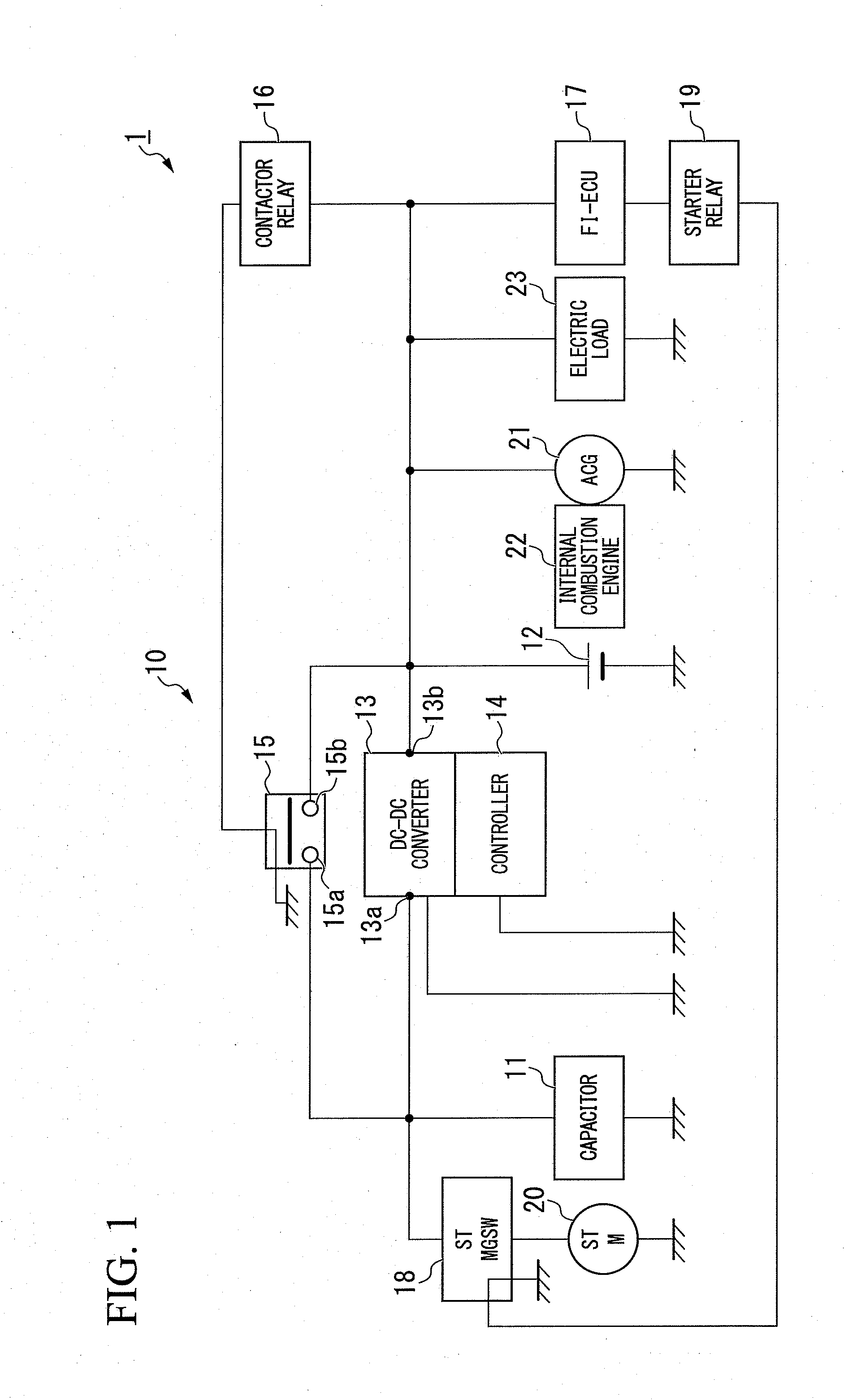
[0039]Hereinafter, a power supply degradation determination apparatus according to an embodiment of the invention will be described referring to the accompanying drawings.

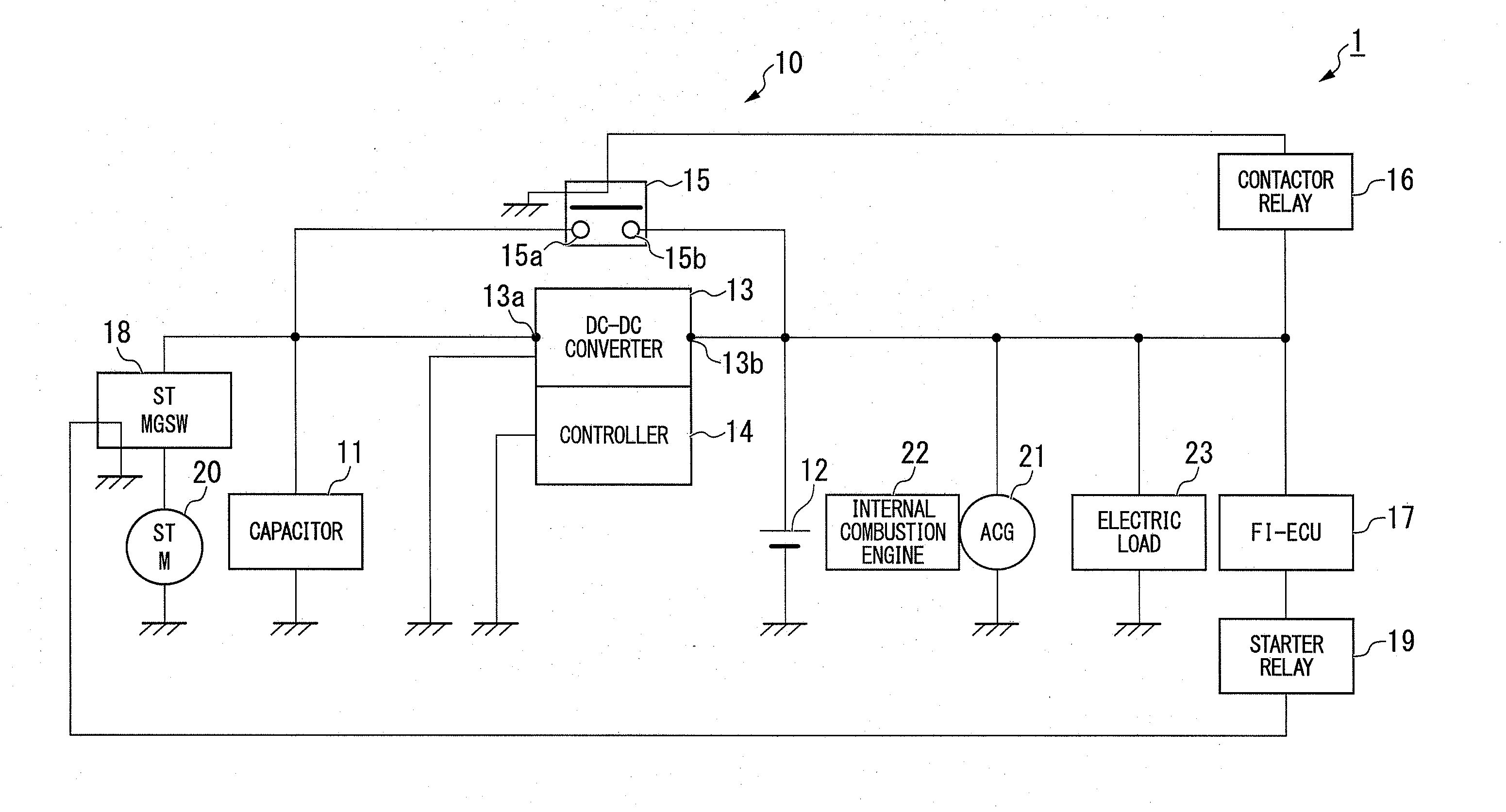
[0040]For example, as shown in FIG. 1, a power supply degradation determination apparatus 10 according to the present embodiment is mounted to a vehicle 1, and the vehicle 1 is configured to include a capacitor (a battery) 11 and a battery 12 as a secondary battery, a DC-DC converter (a charge and discharge control unit) 13, a controller (the charge and discharge control unit, an internal resistance determination unit, a standby unit, a standby prohibition unit) 14, a contactor 15, a contactor relay 16, an FI-ECU (an idle stop unit) 17, a starter magnet switch 18, a starter relay 19, a starter motor (a start-up device) 20, a generator 21, an internal combustion engine 22, and an electric load 23.

[0041]The power supply degradation determination apparatus 10 according to the present embodiment is configured to includ...


PUM


Abstract

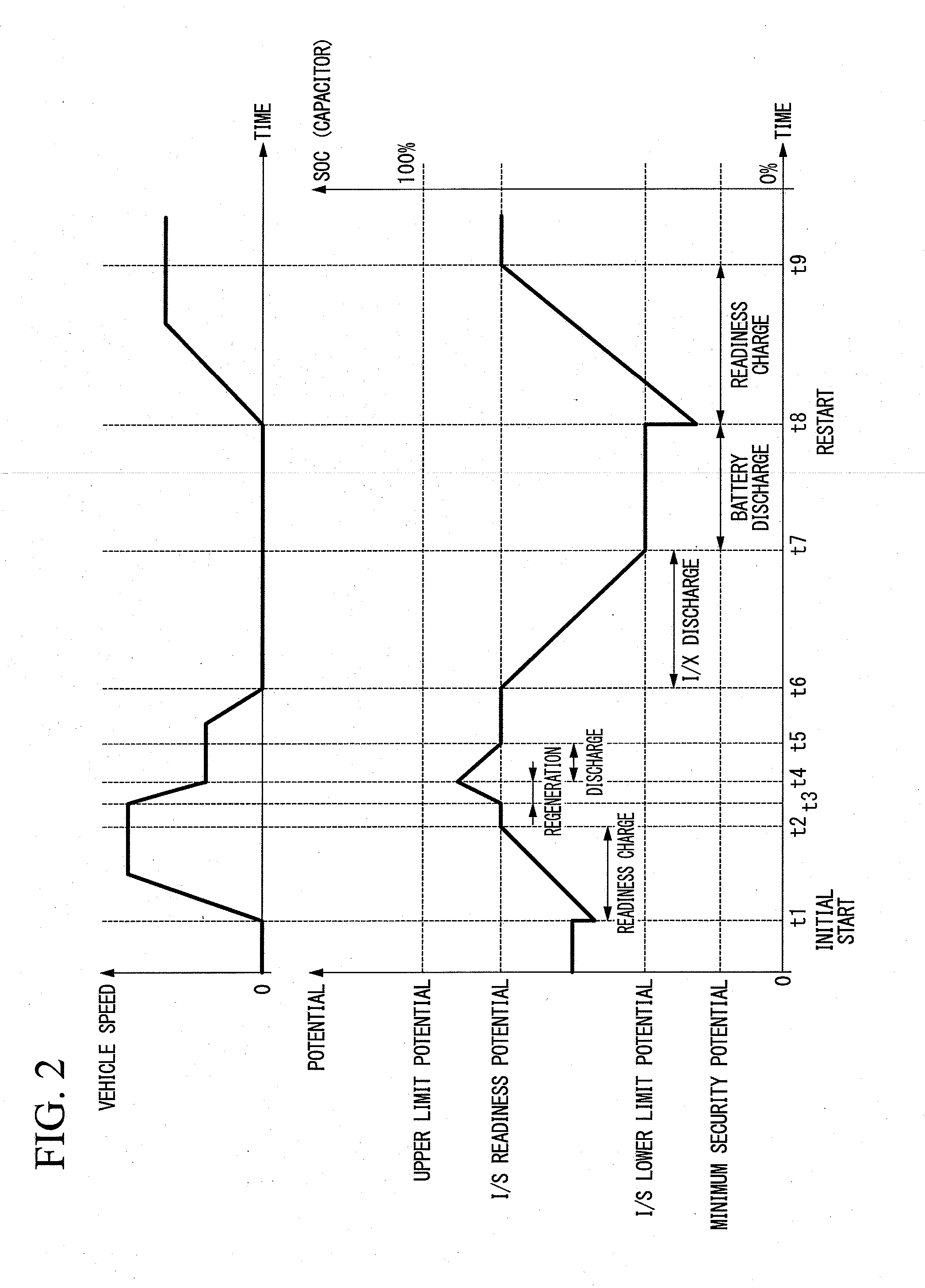
A power supply degradation determination apparatus which is mounted to the vehicle includes a controller and a DC-DC converter that control execution of a charge phase in which a capacitor capable of accumulating regenerative energy of the vehicle is charged and execution of a discharge phase in which the capacitor is discharged. The controller detects the internal resistance of the capacitor using the difference between the terminal voltage and the open circuit voltage of the capacitor during the execution of the discharge phase and the discharge current thereof, determines whether the internal resistance is a predetermined value or more, and delays the execution start of the discharge phase for a predetermined time when the internal resistance is determined to be the predetermined value or more.

Description

CROSS-REFERENCE TO RELATED APPLICATION[0001]Priority is claimed on Japanese Patent Application No. 2012-102593, filed on Apr. 27, 2012, the content of which is incorporated herein by reference.BACKGROUND[0002]1. Field of the Invention[0003]The present invention relates to a power supply degradation determination apparatus.[0004]2. Description of Related Art[0005]Hitherto, apparatuses have been known in which, for example, an open circuit voltage measured at the time of charge interruption during pulse charging of a secondary battery, or the like is used as a nonresistance voltage, and the amount of charge of the secondary battery is estimated based on the nonresistance voltage (see, for example, Japanese Unexamined Patent Application, First Publication No. H9-139236).SUMMARY[0006]Incidentally, according to the above-mentioned apparatus in the related art, since an open circuit voltage is measured during the charge interruption, charging is required to be interrupted.[0007]For this r...

Claims


Application Information

Patent Timeline
IPC IPC(8): B60L11/18
CPCG01R31/3662B60L11/1809H02J7/0057G01R31/3679B60L53/00G01R31/389G01R31/392H02J7/0069Y02T10/70Y02T10/7072Y02T90/14
Inventor TAKAHASHI, YUSUKEABE, TOMOFUMIISHIDA, KENICHIKUBO, KAZUYUKI
Owner HONDA MOTOR CO LTD
Learn More