

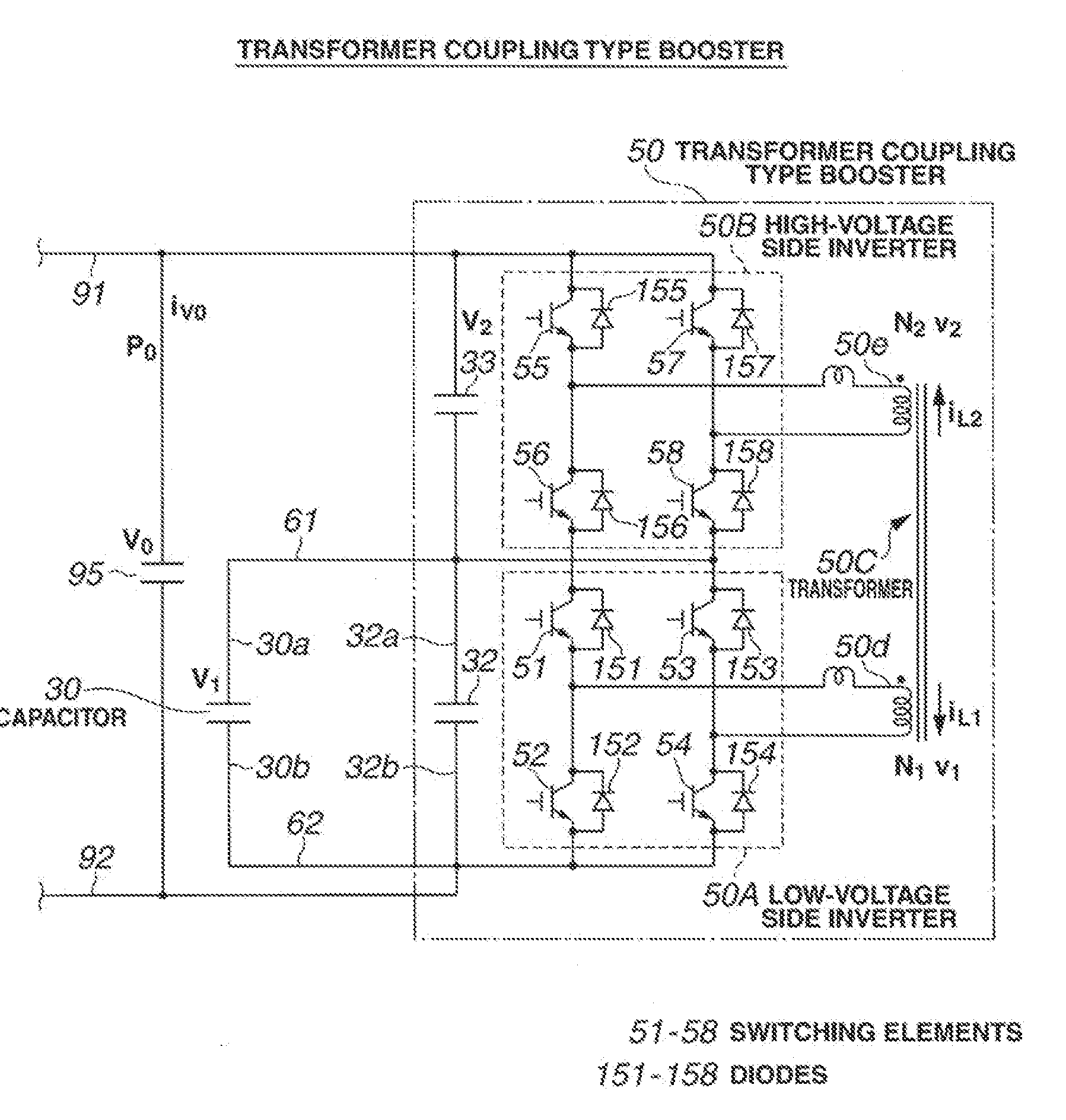
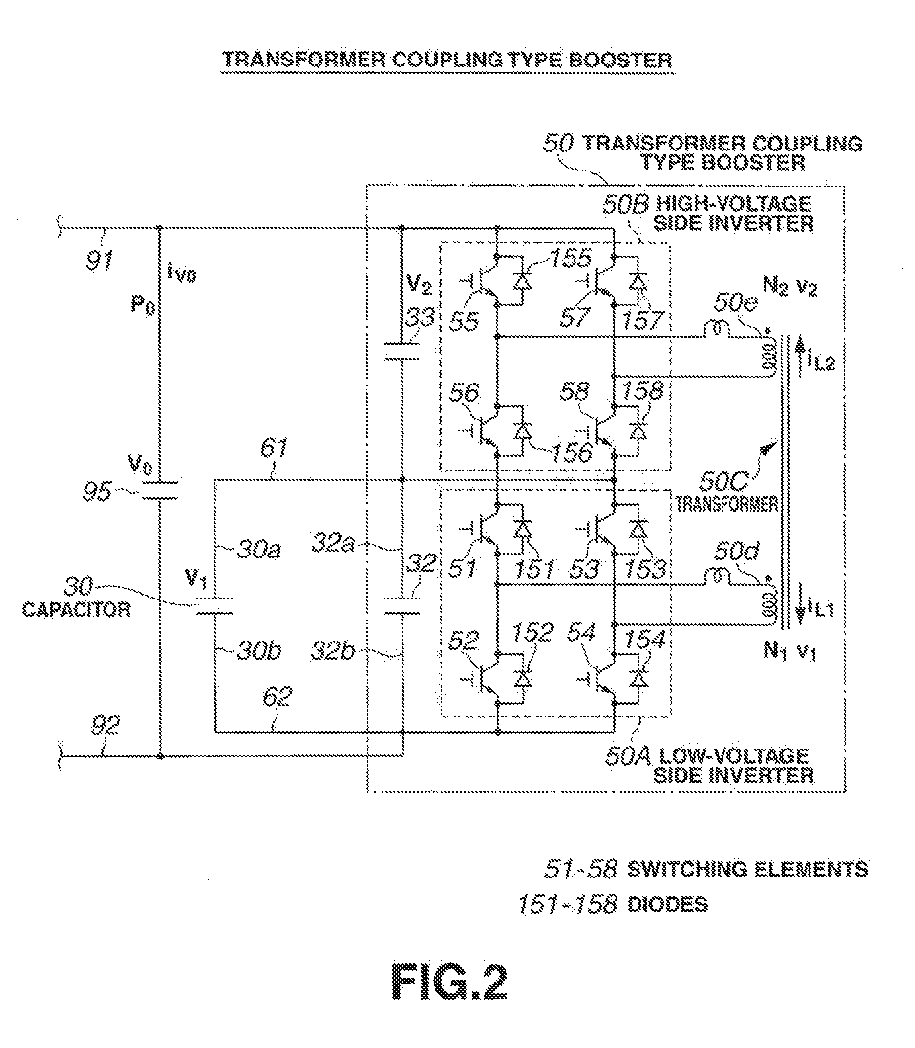
Control device of transformer coupling type booster
a control device and transformer technology, applied in the direction of intermediate ac conversion apparatus, dc-dc conversion, power load or the operating machine motor in a hybrid construction machine that consumes great power in comparison to the engine shaft output, occupies a large area, capacitors with a great capacity that are capable of charging and discharging bulk power, etc., to achieve the effect of improving energy efficiency and inhibiting energy loss
- Summary
- Abstract
- Description
- Claims
- Application Information
AI Technical Summary
Benefits of technology
Problems solved by technology
Method used
Image

Examples
first embodiment
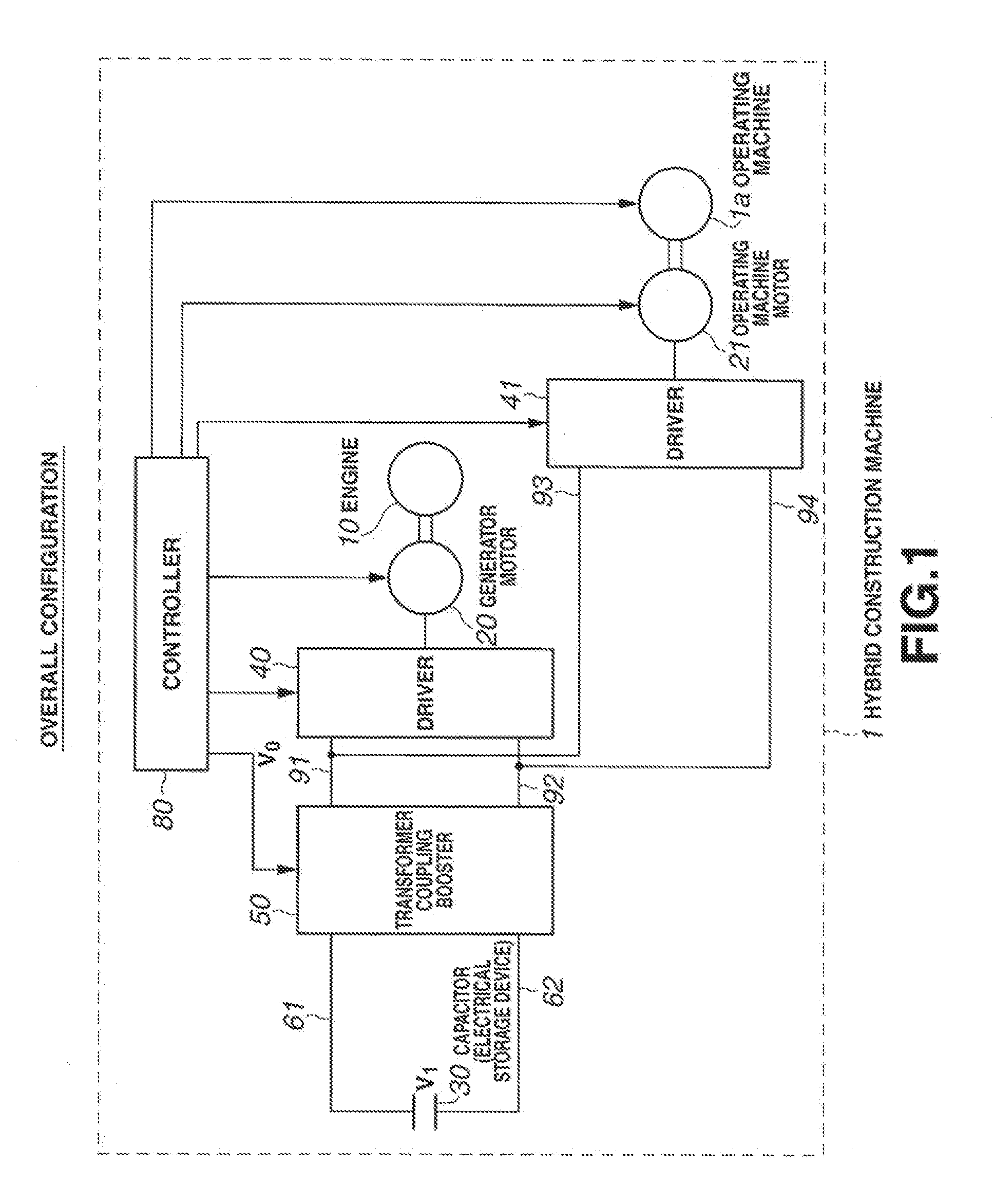
[0059]FIG. 1 shows the overall device configuration according to an embodiment of this invention.
[0060]As shown in FIG. 1, a hybrid construction machine 1 of this embodiment is mounted with an engine 10, a generator motor 20, a capacitor 30, a driver 40, a transformer coupling type booster 50, and a controller 80. The generator motor 20 is driven by the driver 40. The controller 80 controls the driver 40, the generator motor 20 and the transformer coupling type booster 50.
[0061]Moreover, additionally provided is an operating machine motor 21 capable of powering and regenerating an operating machine 1a of the hybrid construction machine 1. The operating machine motor 21 is controlled by the driver 41. The controller 80 controls the driver 41 and the operating machine motor 21.
[0062]A drive shaft of the generator motor 20 is connected to an output shaft of the engine 10. The generator motor 20 performs power generating operations and electrical driving operations. As a result of the g...
second embodiment
[0149]Now, in order to exhibit practical functions as the transformer coupling type booster 50, it is necessary to perform optimal control while giving consideration to various items such as “continuous switching between powering and regeneration,”“output limit,”“loss based on light load at a point away from the equilibrium point,” and “loss at equilibrium point.”
[0150]Thus, tests were conducted by variously changing the respective parameters d, dL, dH described above in order to search for the optimal control. Note that, in the ensuing explanation, all controls are explained as example that were implemented under the foregoing operating conditions 1.
[0151]Values of the phase difference ratio d, the low voltage duty dL, and the high voltage duty dH were changed and first control (conventional control), second control, third control, fourth control, and fifth control were implemented, and their results were examined Consequently, it was discovered that the transformer effective curre...
PUM
 Abstract
Description
Claims
Application Information