[0035]It is an object of the present invention to disclose the avoidance of
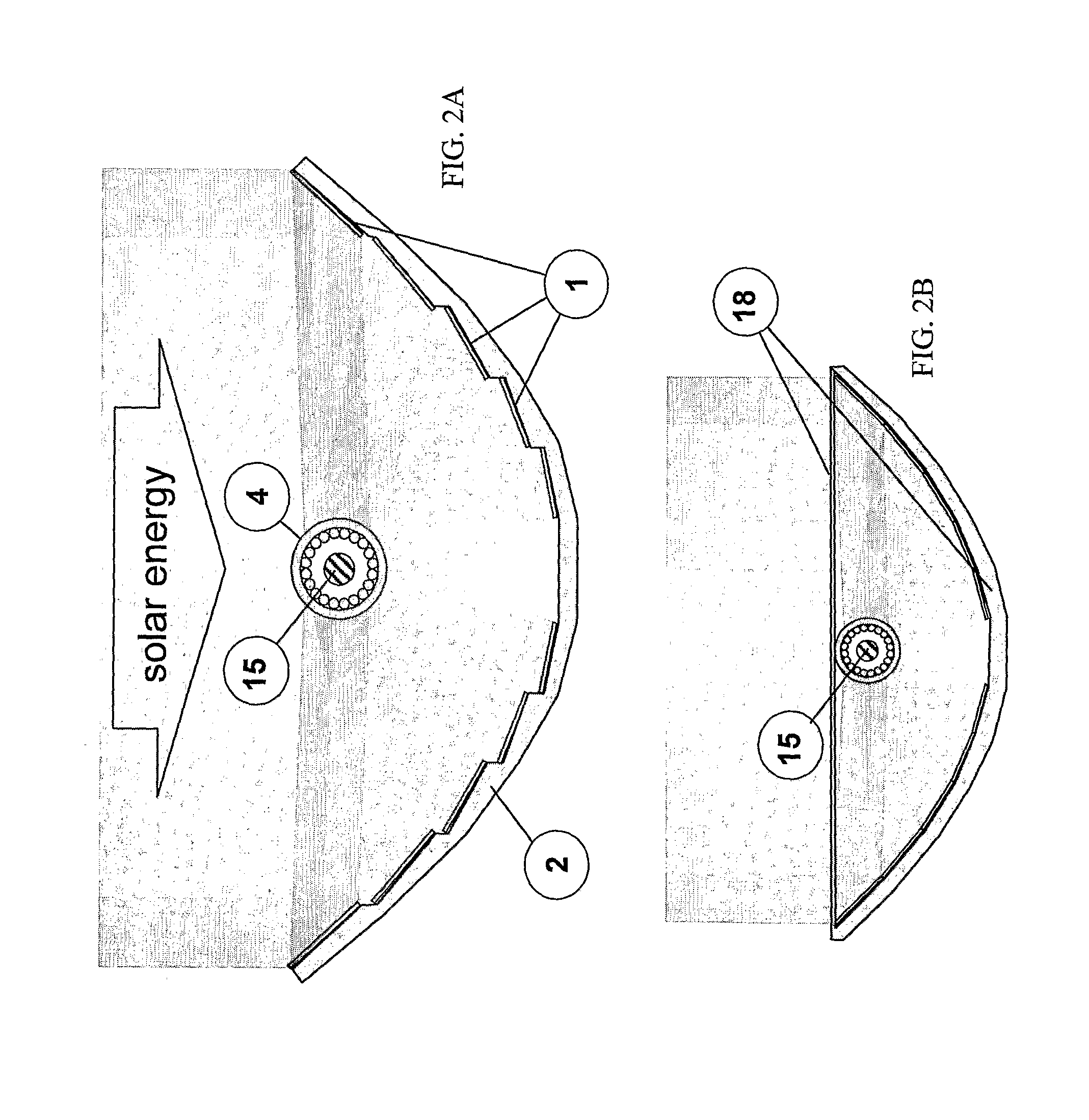
energy loss due to reflections from a low incidence angle of the energy on the receiver. One unappreciated problem of concentrating solar energy is the reflection of incoming energy off of the receiver element. Generally, the receiver element is round as in tubing or
piping (defined below) and the incoming energy is incident to the normal of the tube axis. As such, it encounters a range of incidence angles with respect to the receiver surface. When the incidence angle is low enough, the surface acts as a reflector rather than an absorber and the incident radiation is lost. These same phenomena cause mirages. On the other hand, if the energy is concentrated in too small an area on the receiver, it will heat up giving a large temperature and large
temperature gradient, which then loses heat by radiation,
convection, and conduction to the surroundings. Hence, it is advantageous for the collector to spread the radiation over only a portion of the receiver surface without over-concentrating it in one spot. A strictly
parabolic reflector, whose focus is along the axis of a receiver, will be an ideal candidate since every segment of the reflector will place its energy on a different spot of the receiver and whose incidence is normal. However, great construction and cost
advantage can be attained if one uses a series of narrow
flat panel reflectors, also along a parabolic arc, which reflect energy to a portion of the receiver surface. Hence, this invention encompasses all
flat panel reflecting surfaces which have panel widths to reflect solar energy over some maximum portion of the receive
diameter down to a zero width, which then becomes a strictly
parabolic reflector. All such reflectors are thus advantageous for avoiding the losses associated with reflection and over-concentration.
[0037]Another object of the present invention is to disclose the efficiency gains possible by using a receiver with multiple
layers. Multiple
layers within the receiver allow
excess heat in one layer to be absorbed by a cooler neighbor layer. This reduces losses to surroundings. Although losses to the surroundings can also be reduced by placing the receiver in an enclosed, but transparent casing (preferably at reduced pressure), as is known in the art, multiple
layers allow for quicker transfer of energy to the
working fluid reducing the losses if one chooses not to have such an
enclosure.
[0038]It is another object of the present invention to disclose the
advantage of having the working fluid within the receiver to flow in opposite directions in the different layers. This allows a more uniform distribution of temperature over the length of the receiver, thereby reducing the tendency for the receiver to have a generally hot end and cold end. Of course, there will be a cold fluid entrance and a hot fluid exit, but these may now be placed at the same end which simplifies the design.
[0039]Another object of the present invention is to disclose a solar concentration system which tracks the sun's position so that this maximum heat may be maintained for the most part of
daylight hours. Most existing solar hot water systems use one or more large flat panels which are stationary. Even if they are oriented at the optimum angle for a day, at only one instant during the day is the sun directly overhead. Thus, during the rest of the day, the effective collection area is reduced. Overall, such systems are capable of receiving, at most, around 64% of the available energy. By following the sun, this increases to nearly 100%. Such a concept is known in the art and it is used here. It is also known in the art to rotate the system about the focal point of a
parabolic reflector. Such is the case here where the axis of rotation is along the axis of the receiver. Here, we rotate only the reflector system and leave the receiver stationary. This simplifies the design. It is also possible to rotate the receiver with the reflector.
[0040]Another object of the present invention is to disclose a system, wherein the collector makes use not only of concentrated solar energy but also of
greenhouse effect heating by absorbing indirect solar energy. Such
greenhouse heating is made possible by encasing the receiver in a transparent
enclosure, or, better, encasing the entire system in a transparent
enclosure.
Greenhouse effect heating adds another component to the
energy absorption by
trapping radiation from that scattered by the
atmosphere and any other surrounding
reflective surfaces such a bodies of water, nearby glass buildings, etc. A second
advantage of the transparent enclosure and another object of the present invention is to disclose a system that minimizes the convective losses by housing the receiver in a highly transparent covering. Although, this is not a requirement, a fully optimized system would include such an enclosure to minimize losses to the surroundings as the system heats up.
[0041]Another object of the present invention is to disclose use of photovoltaic (PV) cells at the receiver to generate electrical power. The cells located thus will be receiving concentrated energy from the collector and hence generate more power than a simple
direct exposure to the sun. Virtually any PV
cell will work in the present invention whether high temperature or otherwise, because the
waste heat which would ordinarily raise the
working temperature of the cells, which work at reduced efficiencies at higher temperatures, is carried away by the working fluid within the receiver. Use of concentration on the PV cells reduces the number of required cells and hence considerably lowers the system cost for electrical power generation.

