Camera module

A camera module, the first-line technology, applied in the field of optics, can solve the problems of large camera module, etc., achieve the effect of simple process, wide application range, and prevent wrong assembly or welding direction

Pending Publication Date: 2020-12-11
ZHEJIANG SUNNY SMARTLEAD TECH CO LTD
View PDF0 Cites 0 Cited by
  • Summary
  • Abstract
  • Description
  • Claims
  • Application Information

AI Technical Summary

Problems solved by technology

[0003] The purpose of the present invention is to provide a camera module to solve the problem of large volume of the camera module

Method used


Image

  • Camera module
  • Camera module
  • Camera module

Examples


Embodiment Construction

[0046] In order to more clearly describe the embodiments of the present invention or the technical solutions in the prior art, the following will briefly introduce the drawings that are used in the embodiments. Apparently, the drawings in the following description are only some embodiments of the present invention, and those skilled in the art can also obtain other drawings according to these drawings without creative efforts.

[0047] When describing the embodiments of the present invention, the terms "vertical", "transverse", "upper", "lower", "front", "rear", "left", "right", "vertical", " The orientation or positional relationship expressed by "horizontal", "top", "bottom", "inner" and "outer" is based on the orientation or positional relationship shown in the relevant drawings, which are only for the convenience of describing the present invention and simplifying the description, and It is not to indicate or imply that the device or element referred to must have a particu...


PUM


Abstract

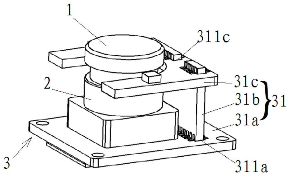
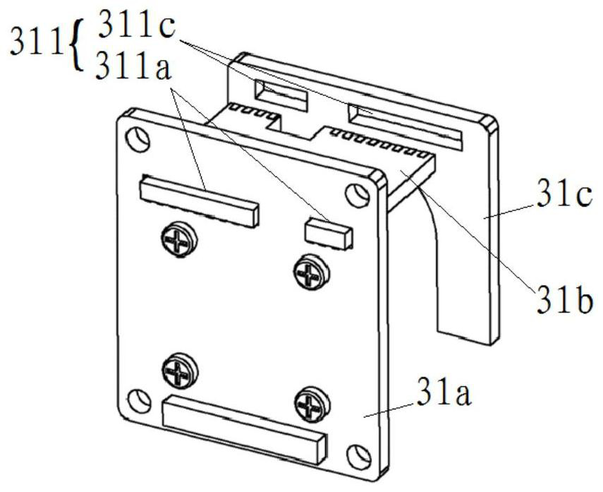
The invention relates to a camera module. The camera module comprises a lens (1), a lens seat (2) and a circuit board frame (3), wherein the lens seat (2) is connected with the circuit board frame (3), and the lens (1) is connected with the lens seat (2); the circuit board frame (3) comprises a plurality of circuit boards (31); and the plurality of circuit boards (31) are stacked in a plug-in manner. According to the camera module, the space structure of the module is reasonably utilized through the circuit board frame of a stacked welding structure, and miniaturization of the camera module isachieved.

Description

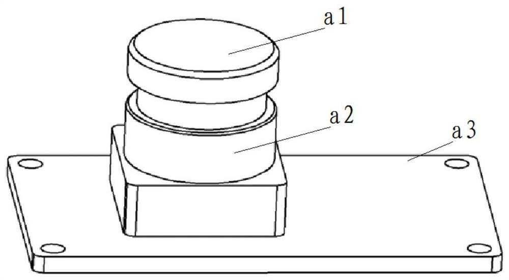
technical field [0001] The invention relates to the field of optics, in particular to a camera module. Background technique [0002] With the development of technology and the automotive industry, on-board cameras are almost standard equipment for every car; and in order to meet the needs of autonomous driving, the number of on-board cameras has also increased. Therefore, in order to meet the complex loading environment, OEMs have increasingly stringent size requirements for on-board cameras, and put forward various requirements for small-sized on-board cameras. Traditional camera modules include: lenses, mirror mounts and circuit boards. The lens is supported on the mirror base, and the mirror base is arranged on the circuit board. In this embodiment, the circuit board is a single board structure, and its structure is simple, but its size is relatively large for the convenience of installing electronic devices, which cannot meet the requirement of miniaturization. Conte...

Claims


Application Information

Patent Timeline
Patent Type & Authority Applications(China)
IPC IPC(8): H04N5/225B60R11/04
CPCB60R11/04H04N23/55H04N23/54
Inventor 丁志张扣文
Owner ZHEJIANG SUNNY SMARTLEAD TECH CO LTD
Why Eureka
Try Eureka