Deburring and chamfering tool

A chamfering tool and deburring technology, which is applied in the direction of manufacturing tools, metal processing equipment, milling machine equipment details, etc., can solve problems such as injuries, burrs, and failure to perform functions, and achieve the effect of uniform processing surface and less load change

Pending Publication Date: 2020-12-11
KATO工机株式会社
View PDF7 Cites 0 Cited by
  • Summary
  • Abstract
  • Description
  • Claims
  • Application Information

AI Technical Summary

Problems solved by technology

[0002] The corners of machined products and cast products usually have burrs, which cannot function and may cause injury if touched
[0003] Therefore, the process of deburring cannot be avoided, but most of them are processed by hand

Method used


Image

  • Deburring and chamfering tool
  • Deburring and chamfering tool
  • Deburring and chamfering tool

Examples


Embodiment Construction

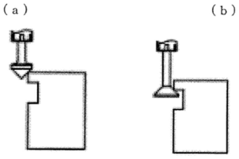
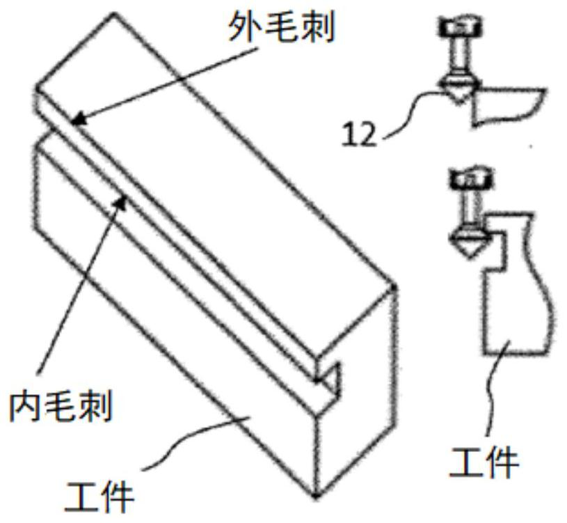
[0026] The roughness of the burr of the cast product is not uniform, and it is difficult to create a program for machining. Therefore, the deburring tool needs to have a telescopic mechanism that has flexibility for unevenness. With the telescopic mechanism, a safe and tidy processed surface can be obtained through a simple procedure.

[0027] Furthermore, from the viewpoint of ease of use, it is necessary that the load change due to expansion and contraction of the expansion and contraction mechanism be small.

[0028] The deburring and chamfering tool related to the present invention will be described in detail below with reference to the accompanying drawings.

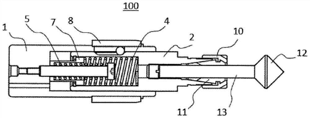
[0029] figure 1 is a sectional view showing the structure of the deburring and chamfering tool 100 according to the present invention. The deburring and chamfering tool 100 consists of a main body 2, a long handle 1 as a connecting device with a drive motor and a tool holder installed on the left side of the main...


PUM


Abstract

A deburring and chamfering tool, characterized in that: the tool has a bidirectional expansion-and-contraction mechanism configured from a first spring and a second spring; each of the first spring and the second spring has a spring constant K (N / mm) that satisfies the relationship K <= F0.H / delta L, where F0 is the standard setting load (N), H is the load change value (%), and delta L is the length-direction change value (mm); and H is 10% or less.

Description

technical field [0001] The invention relates to a deburring and chamfering tool, in particular to a tool capable of continuously deburring and chamfering the surface and the inside of a processed object. Background technique [0002] The corners of machined products and cast products usually have burrs, which cannot function and may cause injury if touched. [0003] Therefore, the process of deburring cannot be avoided, but most of them are processed by hand. [0004] Since manual processing is difficult to ensure safety, and in order to reduce labor and cost, automation of deburring processing is an important issue. Contents of the invention [0005] The technical problem to be solved by the invention [0006] The object of the present invention is to provide a deburring and chamfering tool which is easy to automate the deburring and chamfering process. [0007] means of solving technical problems [0008] The embodiment of the present invention is characterized in th...

Claims


Application Information

Patent Timeline
IPC IPC(8): B23C3/12B23D79/00
CPCB23C3/12B23D79/00
Inventor 阮丁丁陈文铁
Owner KATO工机株式会社
Why Eureka
Try Eureka