Novel mechatronical low load oil pumping machine

A low-load, pumping unit technology, applied in the direction of production fluid, wellbore/well components, earthwork drilling and production, etc., can solve the problem that the gear of the reducer is vulnerable to "backward impact, increase the working load of the motor and reducer, shorten the deceleration To solve problems such as the service life of the device, to achieve the effect of operation balance, energy consumption reduction, and energy saving

Inactive Publication Date: 2014-12-03
TIANJIN DUOLEPENG TECH
View PDF0 Cites 0 Cited by
  • Summary
  • Abstract
  • Description
  • Claims
  • Application Information

AI Technical Summary

Problems solved by technology

At present, the pumping units in service in oil fields are mainly beam pumping units. The overall action of the pumping unit is mainly to rely on the interaction between the beam and the suspension beam to achieve oil pumping. When the suspension point load of the pumping unit is between the upper and lower When the stroke changes greatly, the net torque of the crankshaft of the reducer will appear negative, and the gear of the reducer is vulnerable to "back impact", which increases the working load of the motor and the reducer, and consumes a lot of energy. Reduced service life of the reducer
The pumping unit drives the crank through the motor and the reducer, and the connecting rod drives the beam, the donkey head, the braid, and the sucker rod to work. The whole machine is heavy, the motor load fluctuates greatly, and the power consumption is large, so it cannot adapt to energy saving and consumption reduction. development needs

Method used


Image

  • Novel mechatronical low load oil pumping machine

Examples


Embodiment Construction

[0013] Embodiments of the present invention will be specifically described below in conjunction with the accompanying drawings.

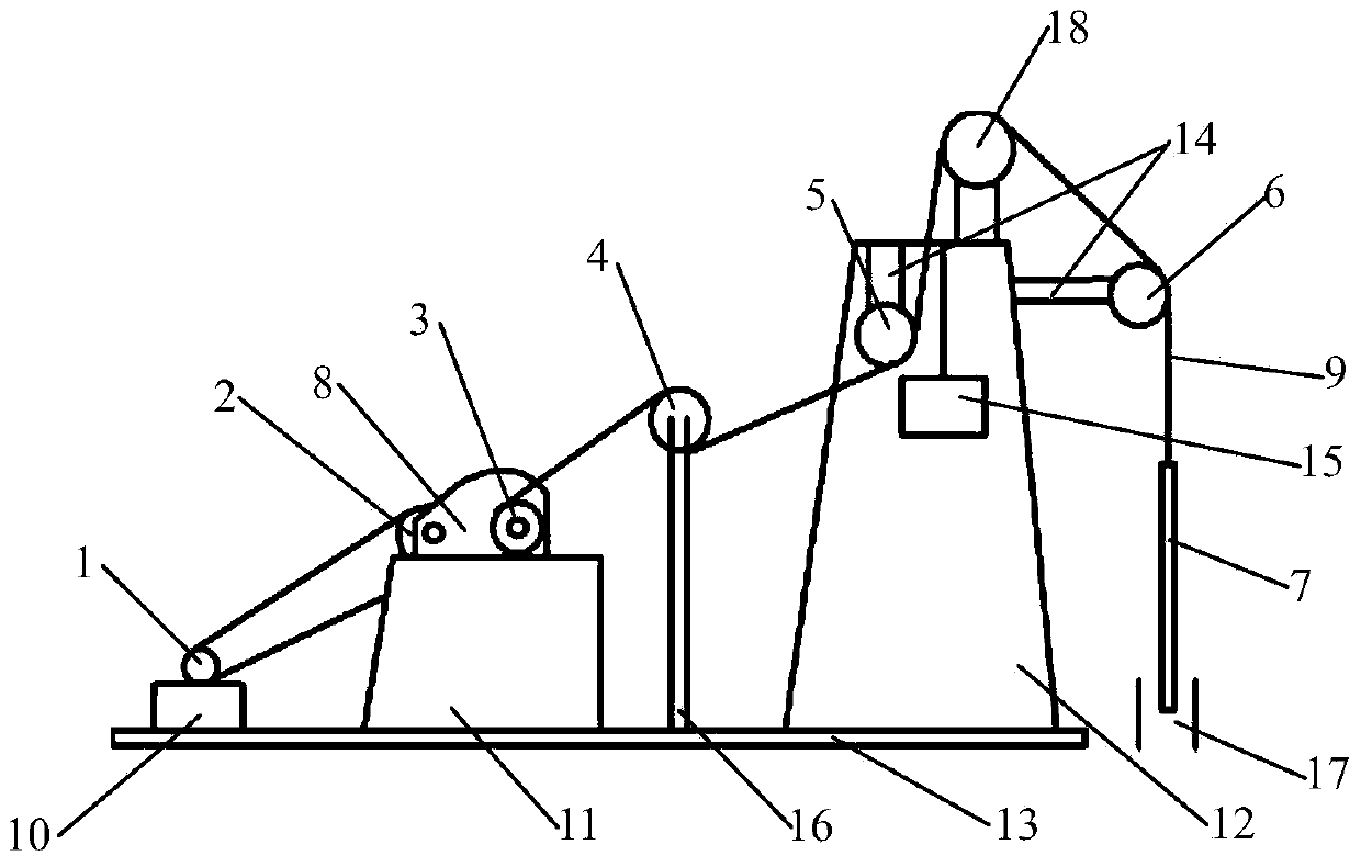
[0014] Such as figure 1 As shown, the present invention provides a novel mechatronic low-load pumping unit, which comprises a motor 1, a pulley 2, a driving pulley 3, a driven pulley 4, a first guide pulley 5, a second guide pulley 6, a pumping pulley Oil rod 7, fixed pulley 18, motor 1 is positioned on base one 10, and the rotating shaft of motor 1 is connected with pulley 2, and pulley 2, driving pulley 3 are connected with reduction motor 81 respectively, and pulley 2, driving pulley 3 are positioned at the reduction motor 81 respectively. At both ends, the reduction motor 81 is located on the base 2 11, the driving wheel 3 and the driven wheel 4 are connected by a rope 9, and the driven wheel 4 is connected to the first guide wheel 5 by a rope 9, and the first guide wheel 5 is used to maintain the position on the first guide wheel. In the direc...


PUM


Abstract

The invention belongs to the field of oil field extraction equipment, and particularly relates to a novel mechatronical low load oil pumping machine. A rotating shaft of the motor is connected with a belt pulley; the belt pulley and a driving wheel are respectively connected with a reducing motor, and are respectively positioned at the two ends of the reducing motor; the driving wheel and a driven wheel are connected through a rope; the driven wheel is connected with a first guide wheel through the rope; the first guide wheel is connected with a fixed pulley through the rope; the fixed pulley is connected with a second guide wheel through the rope; the second guide wheel is connected with a pumping rod through the rope. The novel mechatronical low load oil pumping machine has the benefits that a walking beam and a suspension beam are not needed to be driven to act by the motor, the overall structure of the machine is simple, the mass is reduced, so that the load of the motor is reduced, the energy consumption is less, the oil pumping efficiency is high, and the requirements of energy conservation and consumption reduction development are met.

Description

technical field [0001] The invention belongs to the field of electromechanical integration equipment, and in particular relates to a novel electromechanical integration low-load pumping unit. Background technique [0002] With the continuous progress of society, the human demand for oil is also increasing, and the exploitation of oil is becoming more and more frequent. Generally, the equipment we use to extract oil is the pumping unit. Pumping unit is a kind of machinery and equipment for oil extraction, commonly known as "kowtow machine", which makes oil out of the well by pressurizing. At present, the pumping units in service in oil fields are mainly beam pumping units. The overall action of the pumping unit is mainly to rely on the interaction between the beam and the suspension beam to achieve oil pumping. When the suspension point load of the pumping unit is between the upper and lower When the stroke changes greatly, the net torque of the crankshaft of the reducer wi...

Claims


Application Information

Patent Timeline
Patent Type & Authority Applications(China)
IPC IPC(8): E21B43/00
Inventor 李力杨恒李泰
Owner TIANJIN DUOLEPENG TECH
Why Eureka
Try Eureka