Auxiliary cutting jig on stainless steel bowl basket support

A stainless steel technology on a bracket, applied in the direction of support, manufacturing tools, clamping, etc., can solve the problems of time-consuming marking operations and low production efficiency of bowls and baskets, and achieve the effect of fast marking speed and improved production efficiency

Inactive Publication Date: 2020-12-15
李东亮
View PDF0 Cites 0 Cited by
  • Summary
  • Abstract
  • Description
  • Claims
  • Application Information

AI Technical Summary

Problems solved by technology

Existing conventional bowl basket adopts stainless steel material, there is a kind of such as on the market at present figure 1 The bowl basket 14, the bowl basket 14 is formed by bending and stamping of a stainless steel plate, the middle part of the bowl basket 14 is formed with several slots 141 for placing dishes, and in order to facilitate the positioning of the bowl basket 14 in the pull basket, adjacent Between the bowl baskets 14, there is a dividing plate relatively perpendicular to the bowl basket 14, and the dividing plate realizes the separation between the bowl baskets 14 and can restrain the movement of the bowl basket 14, thereby cutting some slot 142, utilize slot 142 to realize cooperation with the partition; the slot 142 is generally cut and formed by a cutting machine, and the cutting position needs to be marked on the bowl basket 14 when cutting, because there are many slots 142, the marking work It takes a lot of time and the production efficiency of the basket is low

Method used


Image

  • Auxiliary cutting jig on stainless steel bowl basket support
  • Auxiliary cutting jig on stainless steel bowl basket support
  • Auxiliary cutting jig on stainless steel bowl basket support

Examples


Embodiment Construction

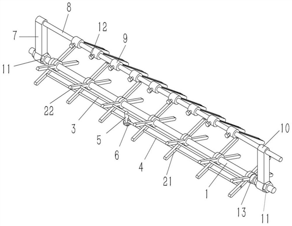
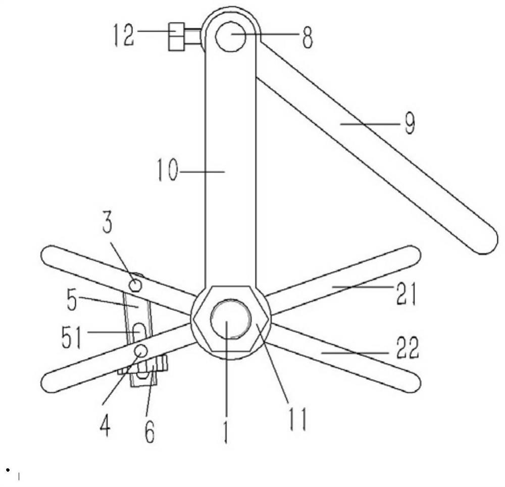
[0020] Example: see Figures 2 to 4 As shown, a cutting auxiliary jig on a stainless steel bowl basket bracket includes a horizontal axis 1, and several X-shaped support frames 2 are inserted on the horizontal axis 1, and the support frame 2 has two intersecting first support rods 21 and The second support rod 22, the middle part of the first support rod 21 is sleeved on the horizontal shaft 1, and the middle part of the second support rod 22 is fixed on the horizontal shaft 1 and abutted against the first support rod 21. The two support rods 22 and the first support rod 21 are respectively plugged and fixed with the first horizontal connecting shaft 3 and the second connecting shaft 4, and the other end of the screw rod 5 is sleeved on the first connecting shaft 3, and the other end is screwed. There is a lock nut 6, an adjustment groove 51 is formed on the screw rod 5, and the second coupling shaft 4 is inserted into the adjustment groove 51 of the screw rod 5;

[0021] The...


PUM


Abstract

The invention discloses an auxiliary cutting jig on a stainless steel bowl basket support. The auxiliary cutting jig on the stainless steel bowl basket support comprises a transverse shaft; a plurality of X-shaped supporting frames are inserted into the transverse shaft; each supporting frame is composed of a first supporting rod and a second supporting rod which are arranged in a crossed mode; and the middle of each first supporting rod is inserted in the transverse shaft in a sleeved mode; the middle of each second supporting rod is inserted and fixed to the transverse shaft in a sleeved mode and abuts against the corresponding first supporting rod; a first connecting shaft and a second connecting shaft which are in the transverse direction are fixed to the second supporting rods and thefirst supporting rods in an inserted connection mode correspondingly; the other end of a screw rod is inserted to the first connecting shaft in a sleeved mode, and a locking nut is connected to the other end of the screw rod in a screwed mode; an adjusting groove is formed on the screw rod; and the second connecting shaft is connected into the adjusting groove of the screw rod an inserted manner.

Description

technical field [0001] The invention relates to the technical field of auxiliary jigs for stainless steel brackets, and more specifically relates to an auxiliary jig for cutting on stainless steel basket brackets. Background technique [0002] The bowl basket, also called the dish basket, is a part of the basket in the cabinet. Existing conventional bowl basket adopts stainless steel material, there is a kind of such as on the market at present figure 1 The bowl basket 14, the bowl basket 14 is formed by bending and stamping of a stainless steel plate, the middle part of the bowl basket 14 is formed with several slots 141 for placing dishes, and in order to facilitate the positioning of the bowl basket 14 in the pull basket, adjacent Between the bowl baskets 14, there is a dividing plate relatively perpendicular to the bowl basket 14, and the dividing plate realizes the separation between the bowl baskets 14 and can restrain the movement of the bowl basket 14, thereby cutti...

Claims


Application Information

Patent Timeline
Patent Type & Authority Applications(China)
IPC IPC(8): B23Q3/06
CPCB23Q3/062
Inventor 李东亮
Owner 李东亮
Why Eureka
Try Eureka