Clutch mechanism and paper feeding structure of printer applying clutch mechanism

A clutch mechanism and clutch technology, applied in printing devices, printing, etc., can solve laborious and other problems

Pending Publication Date: 2020-12-15
NINGBO DELI KEBEI TECH CO LTD
View PDF2 Cites 1 Cited by
  • Summary
  • Abstract
  • Description
  • Claims
  • Application Information

AI Technical Summary

Problems solved by technology

[0004] The defect of this paper feeding mechanism is: when the paper is jammed between the first roller shaft and the second roller shaft, the paper can only be pulled out forcibly. Therefore, it is necessary to arrange a clutch mechanism in which the roller shaft can rotate when the paper is jammed, but the roller shaft will not drive the entire gear set to rotate between the current driving wheel and the driven wheel.

Method used


Image

  • Clutch mechanism and paper feeding structure of printer applying clutch mechanism
  • Clutch mechanism and paper feeding structure of printer applying clutch mechanism
  • Clutch mechanism and paper feeding structure of printer applying clutch mechanism

Examples


Embodiment Construction

[0033] The present invention will be further described in detail below in conjunction with the accompanying drawings and embodiments.

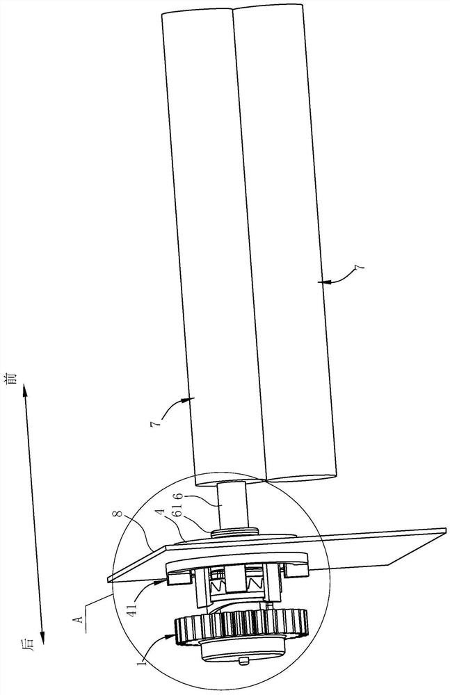
[0034] Such as Figure 1-7 As shown, the paper feed structure of the printer in this preferred embodiment includes a clutch mechanism and two paper feed rollers 7 arranged side by side.

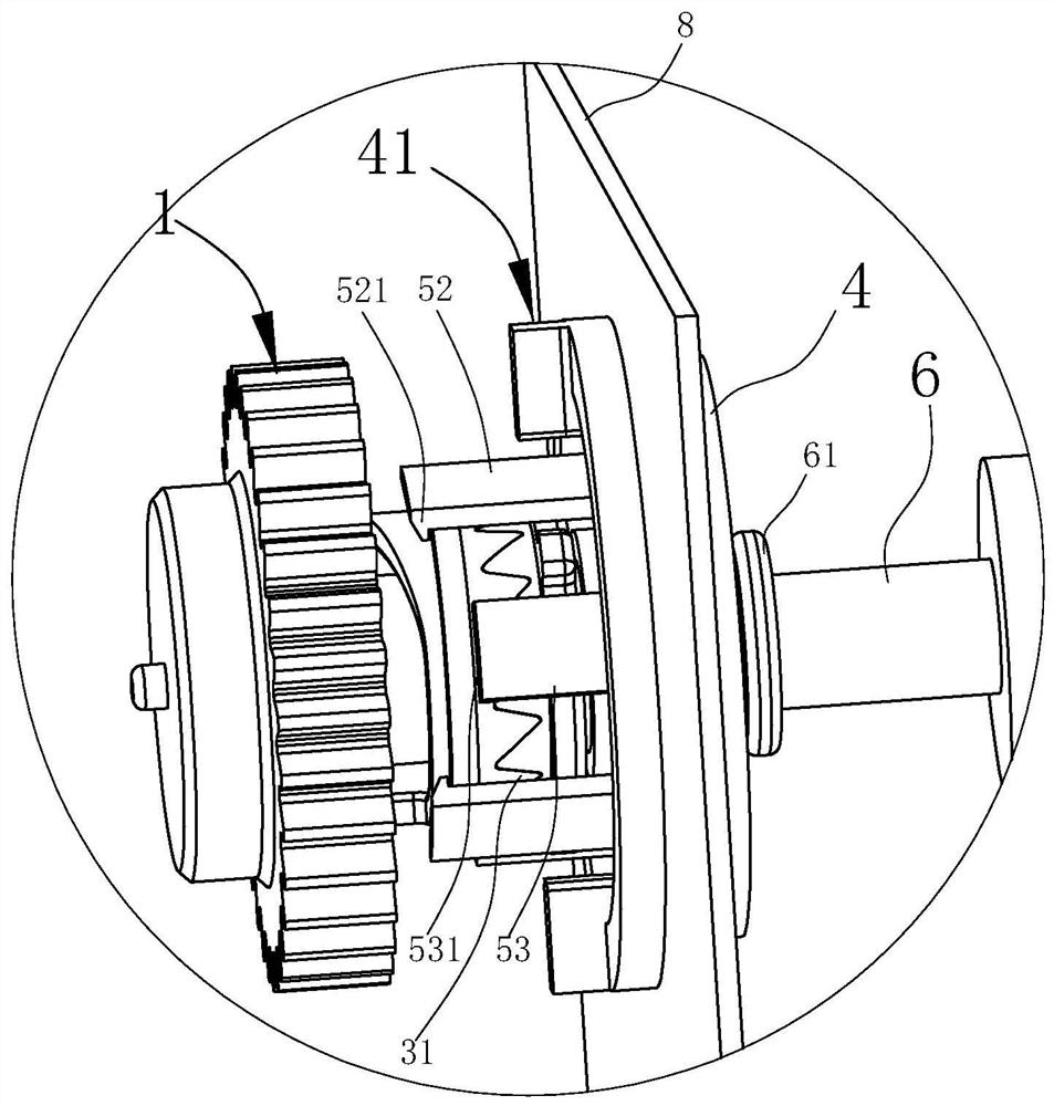
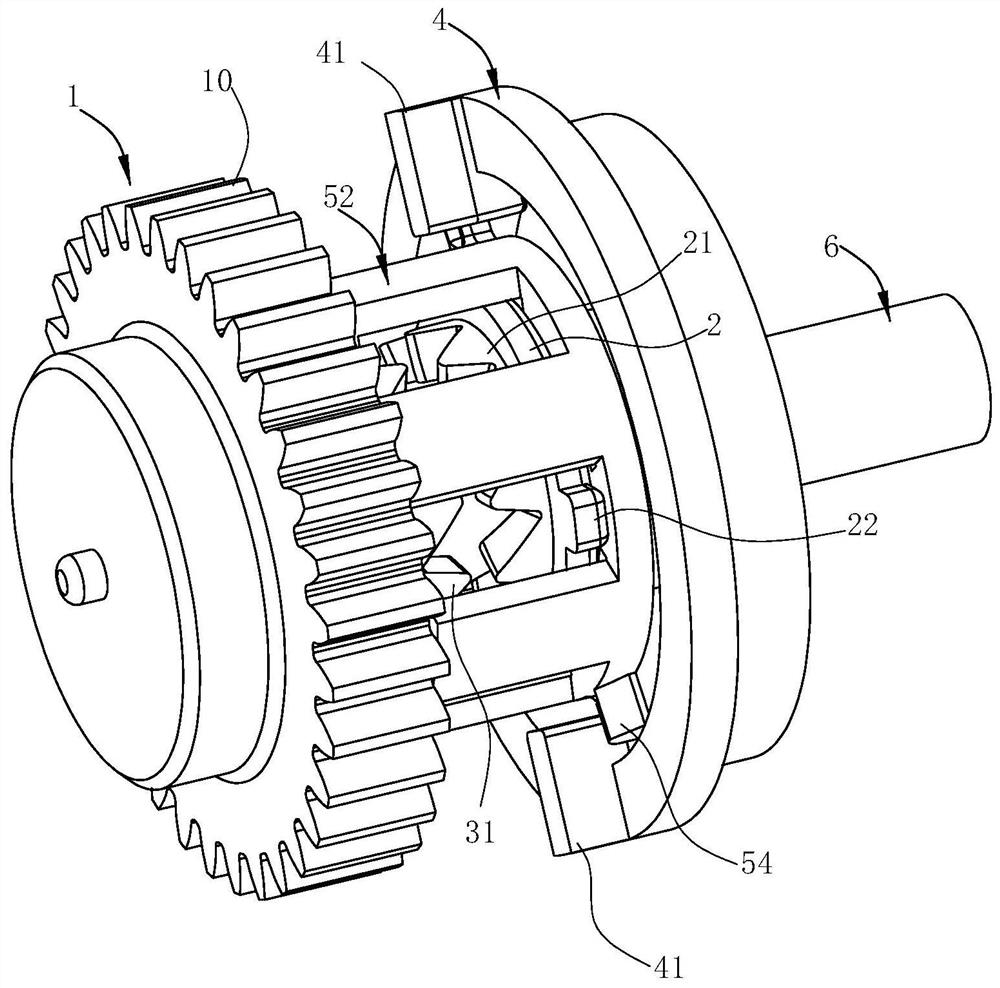
[0035] Wherein the clutch mechanism includes a motor (not shown in the figure), a rotating wheel 1, a first ring gear 2, a second ring gear 3, a fixed frame 4 and a clutch frame 5. In this embodiment, the rotating wheel 1 is provided on the peripheral wall There is a gear with a third tooth portion 10, and the output shaft of the motor is provided with a driving gear (not shown in the figure), and the driving gear is meshed with the running wheel 1, so that the running wheel 1 can rotate around its own axis under the drive of the motor. turn.

[0036] Such as Figure 1-5As shown, the first ring gear 2 and the second ring gear 3 are coaxially arranged with ...


PUM


Abstract

The invention relates to a clutch mechanism and a paper feeding structure of a printer applying the clutch mechanism. The clutch mechanism comprises a rotating wheel, a motor, a first gear ring, a second gear ring, a fixing frame and a clutch frame. The fixing frame is fixedly arranged on the front side of the first gear ring. The rear end of the clutch frame is connected with the second gear ringthrough a connecting structure so that the clutch frame can move in the axial direction of the second gear ring. A limiting structure is arranged between the front end of the clutch frame and the fixing frame, and a positioning structure enabling the clutch frame and the first gear ring to synchronously rotate in the circumferential direction is arranged between the clutch frame and the first gear ring. The clutch frame is located at the position where the limiting structure releases the constraint on the clutch frame in the state that a first tooth part and a second tooth part are engaged, and the clutch frame is located at the position where the clutch frame can only rotate in one direction relative to the fixing frame under the effect of the limiting structure in the state that the first tooth part and the second tooth part are disengaged. The rotating shaft is fixedly connected with the first gear ring. According to the clutch mechanism, the rotating shaft rotates to drive fewer parts to rotate along with the rotating shaft.

Description

technical field [0001] The invention belongs to the technical field of printers, and in particular relates to a clutch mechanism and a paper feeding structure of a printer using the clutch mechanism. Background technique [0002] At present, printers have become an indispensable tool in activities such as life, office, and business. In some fields, batch printing or copying is often performed. [0003] At present, the paper feed roller of the printer is usually driven by a motor, as shown in "A Paper Feed Mechanism for Inkjet Printer" disclosed by the Chinese utility model patent No. CN201721126827. The base frame is provided with a first roller shaft, a first paper feed roller, a second roller shaft, a second paper feed roller and a drive motor, and the first paper feed roller and the second paper feed roller are respectively arranged on the first roller The first roller shaft and the second roller shaft are both arranged on the base frame, and the driving wheel is arrange...

Claims


Application Information

Patent Timeline
Patent Type & Authority Applications(China)
IPC IPC(8): B41J13/076B41J13/02
CPCB41J13/02B41J13/076
Inventor 孙连晨华吉东庞海峰
Owner NINGBO DELI KEBEI TECH CO LTD
Why Eureka
Try Eureka