
A method for selecting the field of view of moving platform scanning radar super-resolution imaging

A technology of super-resolution imaging and scanning radar, which is applied in the direction of instruments, measuring devices, using re-radiation, etc.

Active Publication Date: 2022-07-15
UNIV OF ELECTRONICS SCI & TECH OF CHINA
View PDF19 Cites 0 Cited by
  • Summary
  • Abstract
  • Description
  • Claims
  • Application Information

AI Technical Summary

Problems solved by technology

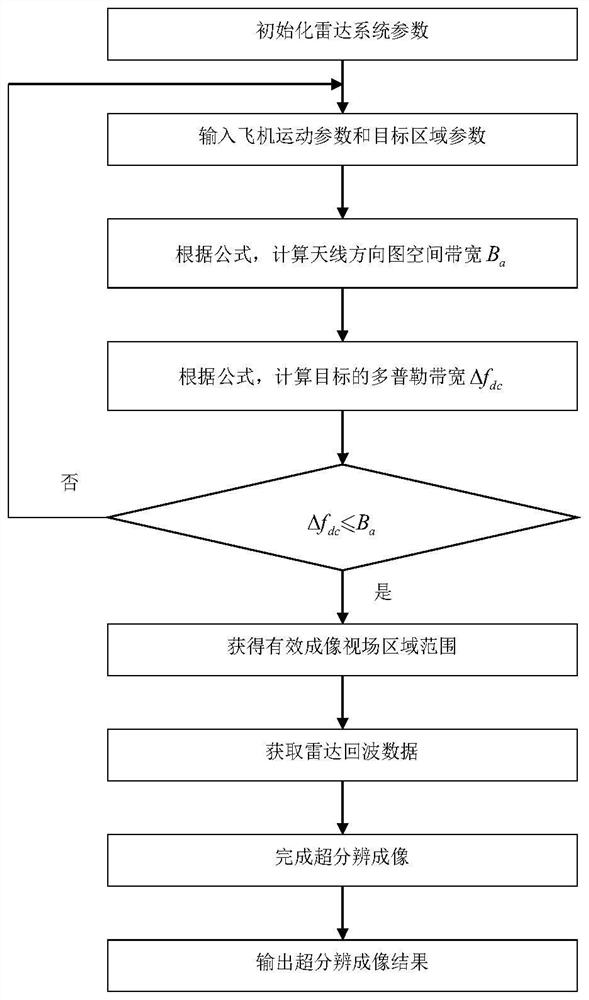
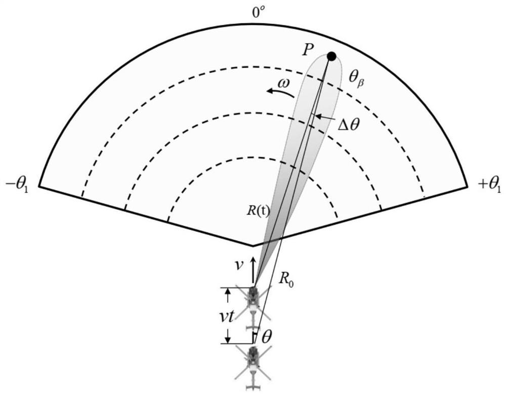
For example, "Chen Hongmeng, etal."Resolution enhancement for Doppler beam sharpening imaging."IET Radar, Sonar and Navigation 9.7(2015):843-851." For the imaging model of Doppler beam sharpening technology, the imaging field of view Restricted to the oblique front view area of ​​the motion platform

Method used


Image

  • A method for selecting the field of view of moving platform scanning radar super-resolution imaging
  • A method for selecting the field of view of moving platform scanning radar super-resolution imaging
  • A method for selecting the field of view of moving platform scanning radar super-resolution imaging

Examples


Embodiment Construction

[0023] In order to facilitate those skilled in the art to understand the technical content of the present invention, the content of the present invention will be further explained below with reference to the accompanying drawings.

[0024] The concrete steps of the present invention are as follows:

[0025] Step 1 Establish the echo model

[0026] In the moving platform scanning radar system, the echo model of the complex convolution modulation can be expressed in matrix form as

[0027] s=Hσ+n (1)

[0028] in, and represent the echo signal, system measurement matrix, target scattering coefficient and additive white noise, respectively, is a symbol commonly used in mathematics. Represents a signal space of N×M dimensions. N, M and K respectively represent the azimuth direction, the range direction and the number of sampling points of the target. The relationship of the three can be expressed as N=K+L-1.

[0029] The system measurement matrix H can be obtained throu...


PUM


Abstract

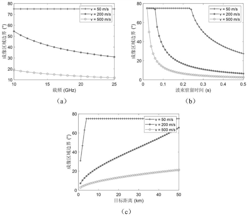
The invention discloses a method for selecting a field of view of a moving platform scanning radar super-resolution imaging, which is applied to the technical field of radar detection and imaging. Aiming at the problem of selecting the applicable range of a moving platform scanning radar super-resolution imaging field of view, the invention analyzes the radar antenna pattern by analyzing the field of view of the moving platform scanning radar. The spatial sampling bandwidth and the Doppler bandwidth of the target in the beam are quantitatively derived, and the applicable boundary of the super-resolution imaging field of view of the airborne scanning radar is quantitatively derived, which is used to select the super-resolution imaging field of view of the moving platform scanning radar; the method of the present invention helps Based on the working mode design and imaging field selection of the airborne scanning radar, it provides help for the effective field of view selection of the super-resolution imaging of the airborne scanning radar.

Description

technical field [0001] The invention belongs to the technical field of radar detection and imaging, and particularly relates to a super-resolution imaging technology suitable for airborne scanning radar. Background technique [0002] Airborne radar super-resolution imaging can improve its azimuth resolution, and has important value in applications such as long-distance detection and formation target discrimination. Usually, the airborne scanning radar obtains a wide range of observation information through the servo system sweeping the antenna. However, in the airborne scanning radar imaging system, due to the limitation of its imaging mechanism, its imaging model is only suitable for a certain imaging field of view under different parameter constraints. The quantitative analysis of the imaging field of view of the airborne radar is helpful for the design of the working mode of the airborne radar system and the selection of the effective imaging field of view. [0003] In ...

Claims


Application Information

Patent Timeline
Patent Type & Authority Patents(China)
IPC IPC(8): G01S13/89G01S13/58G01S7/41G01S13/42
CPCG01S13/89G01S7/418G01S13/58G01S13/426
Inventor 张永伟张永超毛德庆李杰朱俊宇张寅杨建宇黄钰林杨海光
Owner UNIV OF ELECTRONICS SCI & TECH OF CHINA
Learn More