

Zoom lens
A zoom lens and lens technology, applied in the field of zoom lenses, can solve the problems of increasing the number of lenses, the difficulty of the zoom optical system to take into account the high-resolution images without distortion and low cost, and the complex lens structure, etc. Market application prospects, the effect of eliminating back focus drift
- Summary
- Abstract
- Description
- Claims
- Application Information
AI Technical Summary
Problems solved by technology
Method used
Image

Examples
Embodiment approach 1
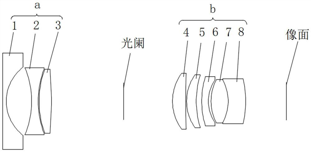
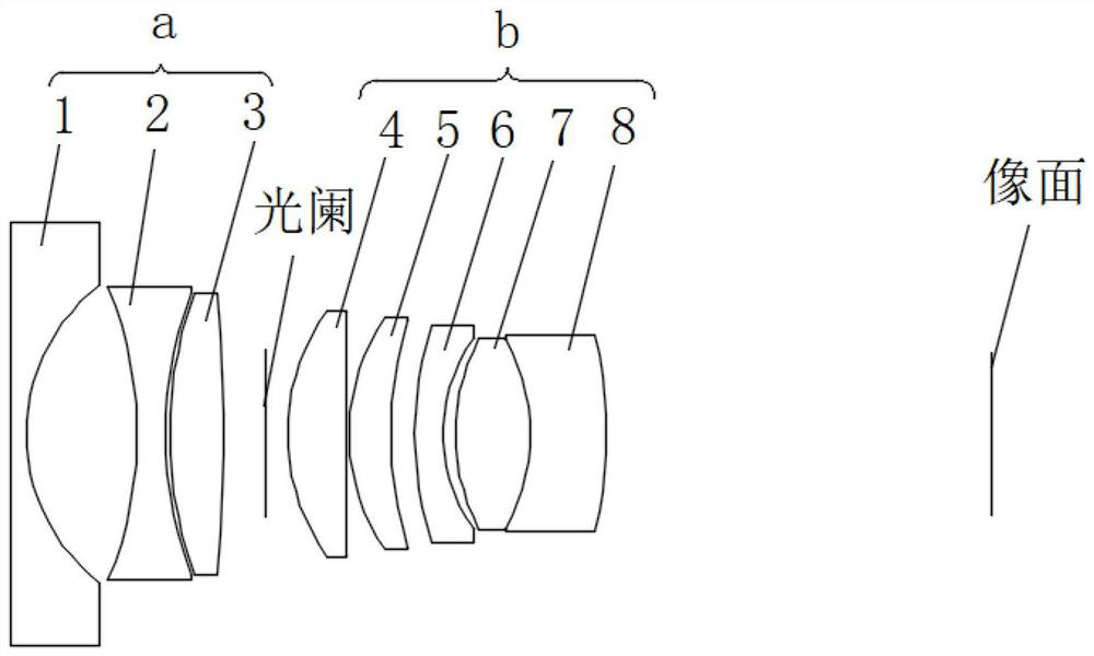
[0053] figure 1 and figure 2 Schematic representations of the structures of the wide-angle end and the telephoto end of the zoom lens in this embodiment are shown respectively. to combine figure 1 and figure 2 As shown, in this embodiment, the first lens group a of the zoom lens includes three lenses, and the second lens group b includes five lenses, wherein the seventh lens 7 and the eighth lens 8 form a cemented lens group.
[0054] The following table 2 lists the relevant parameters of each lens of the present embodiment, including surface type, radius of curvature, thickness, refractive index of material, Abbe number:
[0055] Surface serial number surface type radius of curvature thickness Refractive index Abbe number 1 sphere Infinity 0.61 1.71 50.3 2 sphere 7.638 4.46 3 Aspherical -15.372 1.16 1.53 56.1 4 Aspherical 13.285 0.15 5 Aspherical 11.645 2.15 1.64 23.5 6 Aspherical -360.125 ...
Embodiment approach 2
[0062] Figure 7 and Figure 8 Schematic representations of the structures of the wide-angle end and the telephoto end of the zoom lens in this embodiment are shown respectively. to combine Figure 7 and Figure 8 As shown, in this embodiment, the first lens group a of the zoom lens includes three lenses, and the second lens group b includes five lenses, wherein the seventh lens 7 and the eighth lens 8 form a cemented lens group.
[0063] The following table 4 lists the relevant parameters of each lens of this embodiment, including surface type, radius of curvature, thickness, refractive index of material, Abbe number:
[0064]
[0065]
[0066] Table 4
[0067] What table 5 listed is the aspheric coefficient of each aspherical lens in the present embodiment:
[0068] Surface serial number k a 4
a 6
a 8
a 10
a 12
3 -1.0 6.905E-04 -5.568E-05 1.605E-06 -2.725E-08 1.916E-010 4 -1.0 5.425E-04 -3.712E-05 -2.705E-08 4.078E...
Embodiment approach 3
[0072] Figure 13 and Figure 14 Schematic representations of the structures of the wide-angle end and the telephoto end of the zoom lens in this embodiment are shown respectively. to combine Figure 13 and Figure 14 As shown, in this embodiment, the first lens group a of the zoom lens includes three lenses, and the second lens group b includes five lenses, wherein the seventh lens 7 and the eighth lens 8 form a cemented lens group.
[0073] The following table 6 lists the relevant parameters of each lens of this embodiment, including surface type, radius of curvature, thickness, refractive index of material, Abbe number:
[0074]
[0075]
[0076] Table 6
[0077] What table 7 lists is the aspheric coefficient of each aspheric lens in the present embodiment:
[0078] Surface serial number k a 4
a 6
a 8
a 10
a 12
3 -1.0 9.217E-05 -3.074E-05 1.396E-06 -2.355E-08 1.306E-010 4 -1.0 -3.489E-05 -1.819E-05 5.158E-07 -3.54...
PUM
 Abstract
Description
Claims
Application Information