
Display panel and display device

A display panel and plane technology, which is applied in the direction of electrical components, electric solid devices, circuits, etc., can solve the problems of affecting the display effect of the display panel and increasing the coupling capacitance, so as to improve the display effect and avoid the effect of coupling crosstalk

Pending Publication Date: 2020-12-15
TIANMA MICRO ELECTRONICS CO LTD
View PDF0 Cites 1 Cited by
  • Summary
  • Abstract
  • Description
  • Claims
  • Application Information

AI Technical Summary

Problems solved by technology

When the display device is stretched in a certain direction, the position of some signal lines will change, thereby changing the distance between adjacent signal lines, resulting in an increase in the coupling capacitance between adjacent signal lines, affecting the display panel. The display effect of

Method used


Image

  • Display panel and display device
  • Display panel and display device
  • Display panel and display device

Examples


Embodiment Construction

[0020] The present invention will be further described in detail below in conjunction with the accompanying drawings and embodiments. It should be understood that the specific embodiments described here are only used to explain the present invention, but not to limit the present invention. In addition, it should be noted that, for the convenience of description, only some structures related to the present invention are shown in the drawings but not all structures.

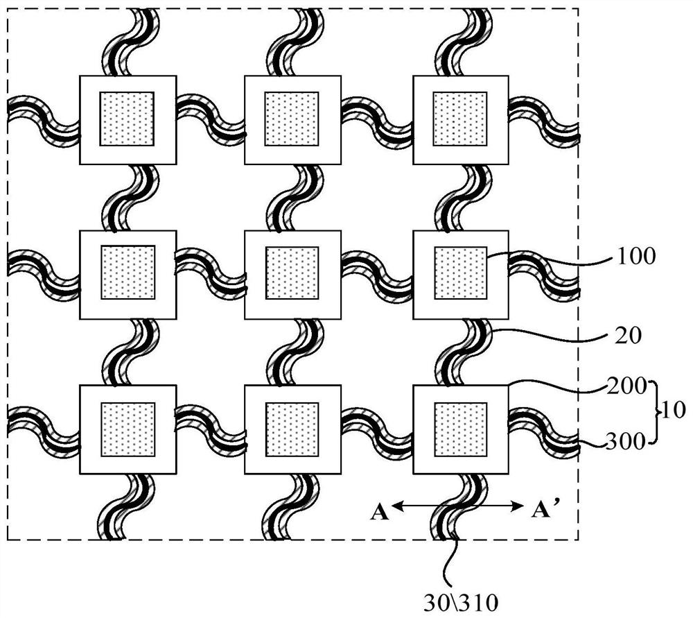
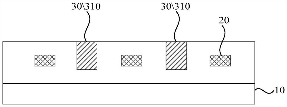
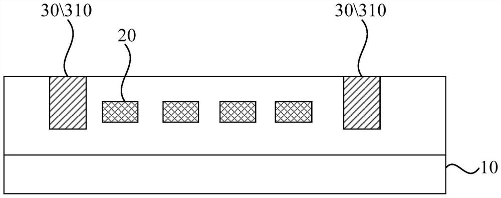
[0021] figure 1 is a schematic structural diagram of a display panel provided by an embodiment of the present invention, figure 2 yes figure 1 The provided schematic diagram of the cross-sectional structure of the display panel along AA', such as figure 1 and figure 2 As shown, the display panel includes: a base substrate 10, the base substrate 10 includes a plurality of island structures 200 separated from each other and a plurality of bridge structures 300 connecting adjacent island structures 200, and the ...


PUM


Abstract

The invention discloses a display panel and a display device. The display panel comprises a substrate, the substrate comprises a plurality of island structures and a plurality of bridge structures connected with the adjacent island structures, the island structures are separated from one another, each bridge structure comprises a plurality of signal lines, and the signal lines being located on theside, close to the light emitting face of the display panel, of the substrate; at least one shielding assembly; the shielding assembly comprising a first part; at least one signal line is arranged between every two adjacent first parts; the extending direction of the first part is perpendicular to the plane where the substrate is located; the shielding assembly is connected to a fixed potential end, and the shielding assembly is insulated from the signal line. In the embodiment of the invention, the signal lines are arranged between the two adjacent first parts, the extension directions of the first parts are perpendicular to the plane where the substrate is located, and the first parts of the shielding assembly are used for weakening the coupling capacitance between the adjacent signal lines parallel to the plane where the display panel is located, so that the display effect of the display panel is improved.

Description

technical field [0001] The present invention relates to the technical field of display panels, in particular to a display panel and a display device. Background technique [0002] Flat panel display devices are widely used due to their small size, light weight and relatively low power consumption. Some flat panel display devices are flexible, so they can be formed into a desired shape by being bent or folded. [0003] Since some flat panel display devices may be stretchable in nature, they may in some cases be stretched in at least one direction. When the display device is stretched in a certain direction, the position of some signal lines will change, thereby changing the distance between adjacent signal lines, resulting in an increase in the coupling capacitance between adjacent signal lines, affecting the display panel. display effect. Contents of the invention [0004] Embodiments of the present invention provide a display panel and a display device, so as to shield...

Claims


Application Information

Patent Timeline
IPC IPC(8): H01L27/12
CPCH01L27/124
Inventor 姜文鑫
Owner TIANMA MICRO ELECTRONICS CO LTD
Learn More