Hoop stamping forming device

A technology of stamping and clamping, applied in the direction of feeding device, positioning device, storage device, etc., can solve the problems that the clamps are not easy to collect, cumbersome to place, and the clamps are not uniform enough

Pending Publication Date: 2020-12-18
方明亮
View PDF7 Cites 1 Cited by
  • Summary
  • Abstract
  • Description
  • Claims
  • Application Information

AI Technical Summary

Problems solved by technology

[0004] In order to overcome the shortcomings of cumbersome placement of clamp raw materials, difficult collection of formed clamps, and uneven forming of clamps, the technical problem

Method used


Image

  • Hoop stamping forming device
  • Hoop stamping forming device
  • Hoop stamping forming device

Examples


Embodiment 1

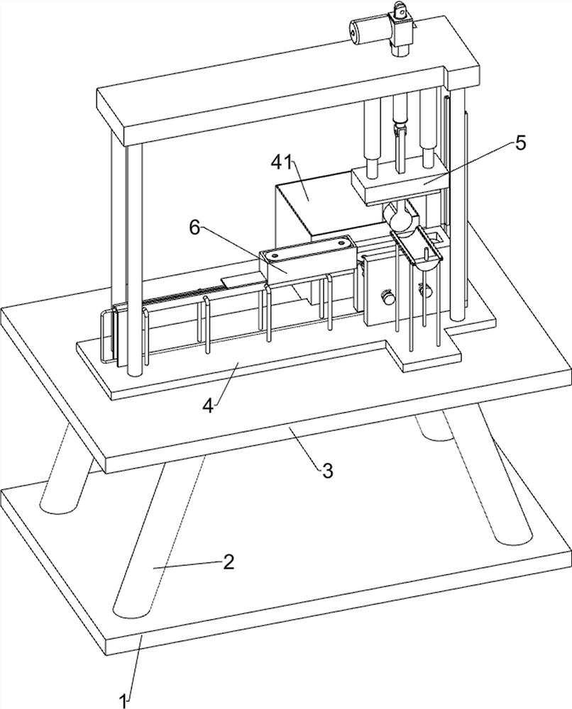
[0063] A clamp stamping and forming device, such as figure 1 As shown, it includes a base 1, a first support column 2, a workbench 3, a backing plate 4, a collection frame 41, a stamping mechanism 5 and a feeding mechanism 6, and two first support columns are connected to the left and right sides of the upper side of the base 1 2. A workbench 3 is connected between the top sides of the first support columns 2, a backing plate 4 is connected to the upper side of the workbench 3, and a collection frame 41 is provided on the upper side and rear of the workbench 3, and the collection frame 41 is in contact with the backing plate 4 A stamping mechanism 5 is connected to the upper side of the backing plate 4 , a feeding mechanism 6 is connected to the upper side of the backing plate 4 , and the feeding mechanism 6 is located between the punching mechanisms 5 .

[0064] When the staff needs to stamp and form the clamp, the staff can first place the clamp raw material in the feeding m...

Embodiment 2

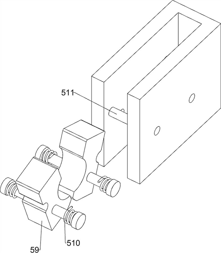
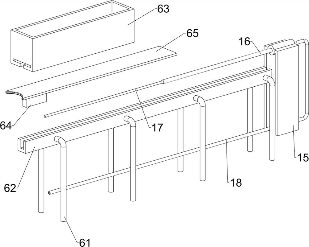
[0066] On the basis of Example 1, such as figure 2 with image 3As shown, the stamping mechanism 5 includes a second support column 51, a top plate 52, a sliding sleeve 53, a sliding column 54, a lower pressing block 55, an inner mold 56, an N-shaped block 57, a connecting shaft 58, an outer mold 59, and an elastic member 510 , a backing column 511 and an electric push rod 512, two second support columns 51 are connected to the left and right parts of the upper side of the backing plate 4, a top plate 52 is connected between the top sides of the second support column 51, and a top plate 52 is connected to the right side of the bottom side of the top plate 52. Two sliding sleeves 53, sliding sleeves 53 are slidingly connected with sliding column 54, the lower side of sliding column 54 is connected with lower pressing block 55, the lower side of lower pressing block 55 is connected with inner mold 56, and the upper side of backing plate 4 is right The N-shaped block 57 is conn...


PUM


Abstract

The invention relates to a forming device, in particular to a hoop stamping forming device. By the adoption of the hoop stamping forming device, hoop raw materials are automatically placed, formed hoops are convenient to collect, and formation of the hoops is uniform. The hoop stamping forming device is characterized by comprising first supporting columns, a workbench, a backing plate, a collecting frame, a stamping mechanism and a feeding mechanism, wherein the two sides of the top of a base are each connected with two first supporting columns, the workbench is connected among the top sides of the first supporting columns, the top side of the workbench is connected with the backing plate, the collecting frame is arranged on one side of the top of the workbench, the collecting frame makescontact with the backing plate, the top side of the backing plate is connected with the stamping mechanism, the top side of the backing plate is connected with the feeding mechanism, and the feeding mechanism is located beside the stamping mechanism. Through cooperation of a downward pressing block, an inner die, an outer die and an electric push rod, the hoop stamping forming device achieves thepurpose of conducting stamping formation of the hoop.

Description

technical field [0001] The invention relates to a forming device, in particular to a clamp stamping forming device. Background technique [0002] The clamp is a kind of hose clamp, which is an American hose clamp in the throat clamp (American hose clamp is also called clamp). The clamp is mainly used to connect grooved pipe fittings, valves and pipeline fittings. A connecting device , used for the clamping function between the quick joints. Generally, the two joints have gaskets, rubber, silicone and PTFE. The clamps have beautiful appearance, easy to use, strong clamping force, good sealing performance, and easy installation. It is mainly used for connection, fastening and sealing of ordinary full rubber hoses, nylon plastic hoses, cloth hoses and water belts of various mechanical equipment and chemical equipment such as vehicles, ships, diesel engines, gasoline engines, fire engines, etc. [0003] The traditional clamp forming method is as follows: the staff holds the mag...

Claims


Application Information

Patent Timeline
IPC IPC(8): B21D22/02B21D43/02B21D45/04
CPCB21D22/02B21D43/02B21D45/04Y02P70/10
Inventor 方明亮
Owner 方明亮
Why Eureka
Try Eureka