Prefabricated building wall truss structure

A technology for building walls and prefabrication, which is applied to truss structures, building components, building structures, etc. It can solve problems such as inconformity with on-site installation conditions and the inability to adjust the width of trusses, achieving good convenience and good practicability , Enhance the effect of supporting ability

Active Publication Date: 2020-12-18
鸿志远科技股份有限公司
View PDF14 Cites 0 Cited by
  • Summary
  • Abstract
  • Description
  • Claims
  • Application Information

AI Technical Summary

Problems solved by technology

[0004] In view of this, the present invention provides a prefabricated building wall truss structure in order to solve the problem that the current trusses cannot be adjusted in width, so that the installation often does not meet the on-site installation conditions.

Method used


Image

  • Prefabricated building wall truss structure
  • Prefabricated building wall truss structure
  • Prefabricated building wall truss structure

Examples


Embodiment Construction

[0028] The following is further described in detail through specific implementation methods:

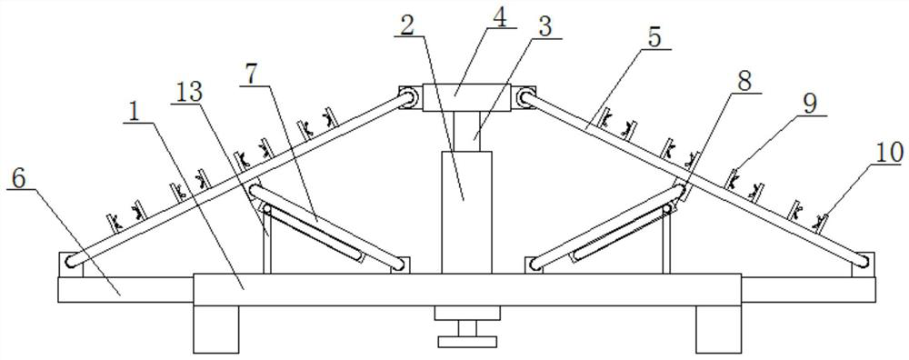
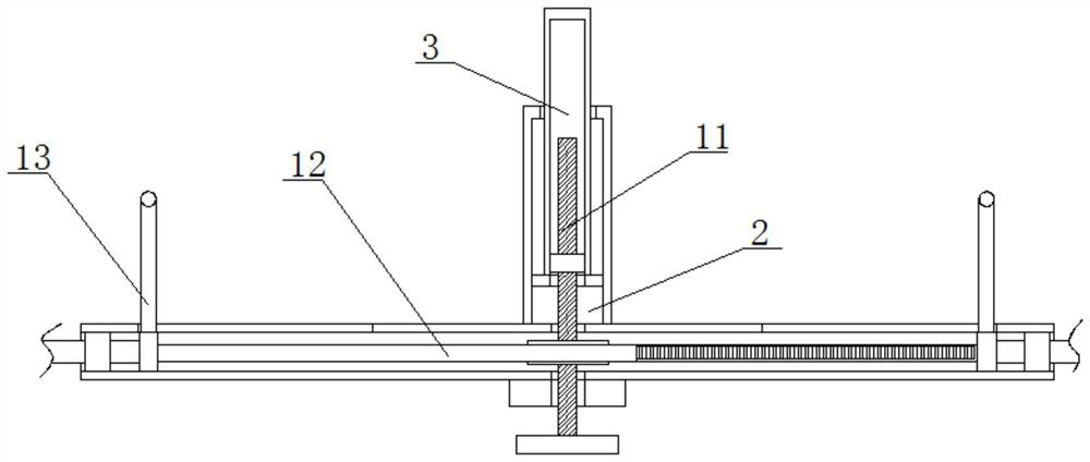
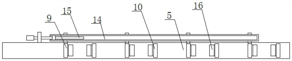
[0029] Such as Figure 1-6 A prefabricated building wall truss structure shown includes a support tube 1, a support cover 2 is fixedly installed on the top of the support tube 1, and a lift cover 3 is slidably connected to the support cover 2, and the top of the lift cover 3 extends to The top of the support cover 2 is fixedly installed with a connecting pipe 4, and both sides of the connecting pipe 4 are rotatably connected with a supporting beam 5, and two moving columns 6 are symmetrically slidingly connected in the supporting tube 1, and the two moving columns 6 are far away from each other. One end extends to the outside of the support tube 1 and is respectively connected to the two support beams 5 in rotation. The inner wall of the support tube 1 is rotatably connected to a drive screw 11, and the top end of the drive screw 11 extends into the lift cover 3 and is connected to t...


PUM


Abstract

The invention relates to the field of buildings, in particular to a prefabricated building wall truss structure. A lifting cover is slidably connected into a supporting cover at the top of a supporting pipe, the top of the lifting cover extends to the position above the supporting cover and is fixedly provided with a connecting pipe, two moving columns are symmetrically and slidably connected intosupporting beams rotationally connected to the two sides of the connecting pipe, and the ends, far away from each other, of the two moving columns extend to the outer side of the supporting pipe andare rotationally connected with the two supporting beams correspondingly; and the inner wall of the supporting pipe is rotationally connected with a transmission screw rod, the top end of the transmission screw rod extends into the lifting cover and is in threaded connection with the inner wall of the lifting cover, the bottom end of the transmission screw rod extends to the position below the supporting pipe, and the transmission screw rod is in transmission connection with the two moving columns correspondingly. The two moving columns can be driven to be close to or far away from each otherby rotating the transmission screw rod so that the width of the device can be adjusted, the device can adapt to various field mounting environments in the using process, and the device has good convenience and practicability.

Description

technical field [0001] The invention relates to the technical field of buildings, and relates to a prefabricated building wall truss structure. Background technique [0002] Reinforced Concrete Truss A truss made of reinforced concrete or prestressed concrete material. Reinforced concrete trusses are mostly used for roof trusses, towers, and sometimes trestles and crane beams. Because the tie rods of reinforced concrete trusses often crack under the load, they are only used for trusses with light loads and small spans. After the 1950s, with the development of prestressed concrete technology, prestressed concrete trusses have been widely used in China for trusses with large spans and heavy loads. [0003] However, the current trusses cannot be adjusted in width, which often causes problems that do not meet the on-site installation conditions during installation. Therefore, we propose a prefabricated building wall truss structure to solve the above-mentioned problems. Cont...

Claims


Application Information

Patent Timeline
Patent Type & Authority Applications(China)
IPC IPC(8): E04B2/00E04C3/02E04B1/343
CPCE04B2/00E04C3/02E04B1/343
Inventor 胡敏
Owner 鸿志远科技股份有限公司
Why Eureka
Try Eureka