A window sash auxiliary installation device
A technology for installing devices and window sashes, which is applied to lifting devices, buildings, building structures, etc., can solve problems such as inconvenient operation and excessively heavy window sashes, and achieve the effects of flexible use, smooth movement, and reduced manual labor.
- Summary
- Abstract
- Description
- Claims
- Application Information
AI Technical Summary
Problems solved by technology
Method used
Image
Examples
Embodiment 1
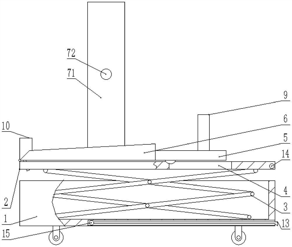
[0031] A window saw auxiliary mounting device, such as figure 1 As shown, including the base 1 with a roller, the device is moved by a roller, saving manpower, and a self-locking device on the roller, and the wheel is in a self-locking state without moving the device, preventing the device from moving freely, avoiding Danger.
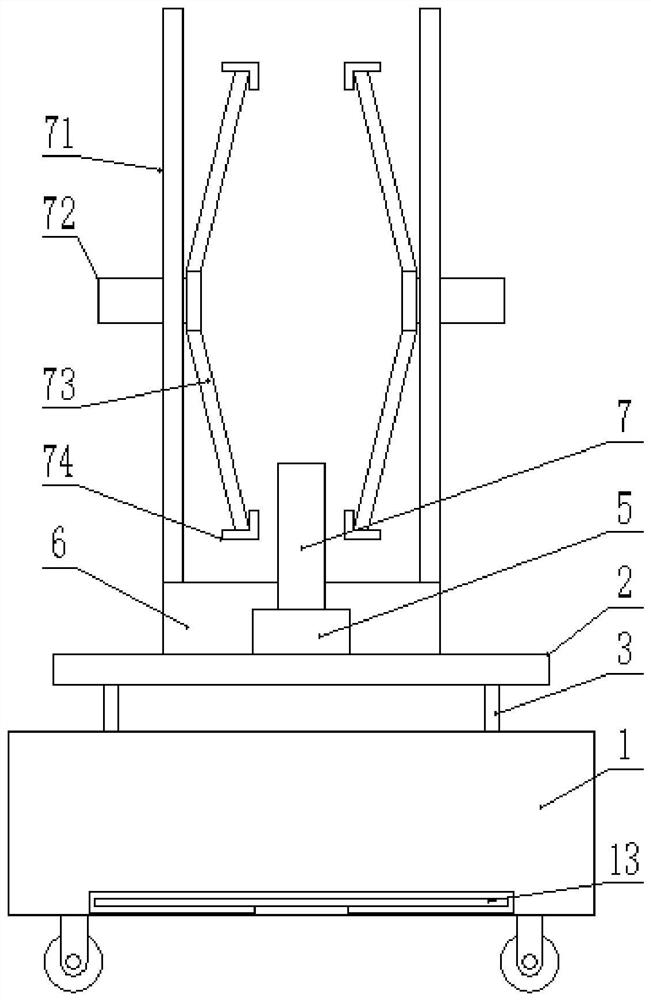
[0032] like figure 1 As shown, there is a mounting plate 2 on the base 1, and the base 1 and the mounting plate 2 are provided with a shearing mechanism 3 that moves up and down to the mounting plate 2, the shear mechanism 3 includes a support rod, a hinge shaft, and a cylinder, which is compared. Common, there is no more details here. The shearing mechanism 3 is used to move the mounting plate 2 upward from the base 1, and the mounting plate 2 moves the mounting plate 6 and the window fan movement, thereby so that the window sector is in a height of easy installation.
[0033] like figure 1 As shown, the mounting plate 2 is provided with a slide 14, the ch...
Embodiment 2
[0044] Based on the first embodiment, the shearing mechanism 3 moves the window fan to the highly installed height, the user needs to stand with the height of the outside of the table, the table or tool is suitable for installation, and then look for other tools more troublesome. So, if figure 1 and figure 2 As shown, the base 1 side is provided with a pull-out connection plate 13, and the bottom side of the base 1 is provided on the bottom side of the base 1, which does not occupy too much space and does not affect the movement of the roller, and is convenient.
[0045] The connecting plate 13 is provided with a plurality of projections, and the user can increase the friction when the user walks on the connecting plate 13, and prevents the slip phenomenon. Alternatively, the connecting plate 13 may also be a structure similar to a ladder, and the user can be moved by the connecting plate 13 to the mounting plate 2 to facilitate subsequent mounting filaments.
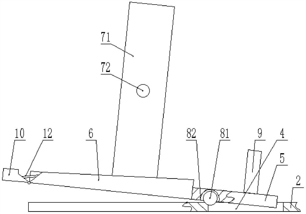
[0046] like figure ...
Embodiment 3
[0048] Based on Example 1 and Example 2, the connecting plate 13 may also be a lockable telescopic plate structure, and a plurality of chutes 14 are provided on one side of the mounting plate 2, the chute 14 The straight slot is different from the angle of tilting. This configuration can change the angle of the lower end of the connecting plate 13 and the ground, so that the slope / slope of the connecting plate 13 is slow, the smaller the inclination of the connecting plate 13, and the convenient user moves to the mounting plate 2.
[0049] The user can set the connecting plate 13 to the unlocked state according to the environment in the construction site, and then insert the slider 15 at one end of the connecting plate 13 to the suitable chute 14, and the connection plate 13 is in a tilted state under the limit of the straight slot. One end of the connecting plate 13 is in contact with the ground, and then the connecting plate 13 is adjusted to the locked state and can be used. ...
PUM
 Abstract
Description
Claims
Application Information
 - R&D
- Intellectual Property
- Life Sciences
- Materials
- Tech Scout
- Unparalleled Data Quality
- Higher Quality Content
- 60% Fewer Hallucinations
Browse by: Latest US Patents, China's latest patents, Technical Efficacy Thesaurus, Application Domain, Technology Topic, Popular Technical Reports.
© 2025 PatSnap. All rights reserved.Legal|Privacy policy|Modern Slavery Act Transparency Statement|Sitemap|About US| Contact US: help@patsnap.com


