Engineering machinery railway running auxiliary device

A technology for construction machinery and auxiliary devices, applied in the direction of lifting devices, lifting frames, etc., can solve the problems of difficult operation, poor maneuverability, and high cost, and achieve the effects of extending the driving range, maneuvering flexibility, and low cost.

Inactive Publication Date: 2020-12-25
刘同宇
View PDF0 Cites 0 Cited by
  • Summary
  • Abstract
  • Description
  • Claims
  • Application Information

AI Technical Summary

Problems solved by technology

[0002] Current construction machinery such as excavators and loaders do not have the function of running on the railway. When the railway is damaged due to disasters such as landslides and mudslides, the above-mentioned construction machinery cannot pass because it does not have the function of running on the railway. When the railway travels to the emergency repair site, it can only be transported to the emergency repair site by road or railway truck. Some emergency repair sites are not accessible by road, so construction machinery such as excavators and loaders cannot be transported to the emergency repair site by road, and can only be transported to the emergency repair site by railway trucks. However, there are many disadvantages in the transportation of railway wagons, such as the difficulty of loading and unloading excavators, loaders and bulldozers on the wagons, poor maneuverability and high cost. However, when the railway is damaged due to disasters such as landslides and mudslides, the railway circuit will often be damaged, which limits the use of railway freight cars.

Method used


Image

  • Engineering machinery railway running auxiliary device
  • Engineering machinery railway running auxiliary device

Examples


Embodiment Construction

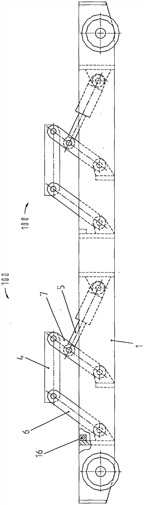
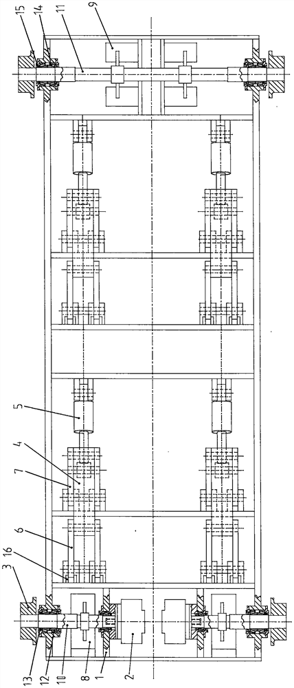
[0028] The present invention will be further described below in conjunction with accompanying drawing and specific embodiment, so that those skilled in the art can more clearly understand the scheme of the present invention, the specific implementation mode provided in the accompanying drawing is only a kind of implementation of the technical scheme provided by the present invention example, but does not limit the protection scope of the present invention, as attached figure 1 And attached figure 2 As shown, a construction machinery railway driving auxiliary device includes:

[0029] Frame 1, hydraulic motor 2, track wheel 3, pallet 4, hydraulic cylinder 5, support arm I6, support arm II7, brake device I8, brake device II9, driving shaft 10, driven shaft 11, bearing I12, rotating shaft Oil seal I13, bearing II14, rotary shaft oil seal II15, limit block 16.

[0030] Frame 1, the lower part of both sides of the front end and the rear end are respectively rotatably equipped wi...


PUM


Abstract

The invention provides an engineering machinery railway running auxiliary device. The device comprises a rack, two hydraulic motors and four lifting devices, wherein a plurality of rail wheels are rotatably installed on the lower portions of the two sides of the front end and the rear end of the rack respectively; the two hydraulic motors are in transmission connection with the rail wheels; and the four lifting devices are used for lifting the bottom surface of a vehicle frame of an excavator or the bottom surface of an axle of a loader. Two brake devices I and two brake devices II are arranged on the rack and used for braking. When the engineering machinery railway running auxiliary device is used, the excavator or the loader can be used to hang the engineering machinery railway running auxiliary device on a rail, then the excavator or the loader runs to the upper portion of the rail, the bottom faces of the vehicle frame of the excavator or the axle of the loader are supported by thelifting devices, and the excavator or the loader is lifted to be separated from the ground. Then the hydraulic motors are controlled to drive the engineering machinery railway running auxiliary device to lift the excavator or the loader to run on the rail, and the engineering machinery railway running auxiliary device is mainly suitable for railway emergency maintenance work.

Description

technical field [0001] The invention relates to an auxiliary configuration of construction machinery, in particular to an auxiliary device for construction machinery vehicles such as excavators or loaders whose inner wheelbase is larger than the total width of two rails of the railway, running on the railway. Background technique [0002] Current construction machinery such as excavators and loaders do not have the function of running on the railway. When the railway is damaged due to disasters such as landslides and mudslides, the above-mentioned construction machinery cannot pass because it does not have the function of running on the railway. When the railway travels to the emergency repair site, it can only be transported to the emergency repair site by road or railway truck. Some emergency repair sites are not accessible by road, so construction machinery such as excavators and loaders cannot be transported to the emergency repair site by road, and can only be transporte...

Claims


Application Information

Patent Timeline
Patent Type & Authority Applications(China)
IPC IPC(8): B66F7/08B66F7/28
CPCB66F7/0641B66F7/08B66F7/28
Inventor 刘同宇
Owner 刘同宇
Why Eureka
Try Eureka