
Display device and control method thereof

A display device and display area technology, which is applied to instruments, nonlinear optics, optics, etc., can solve problems such as the inability to display in the apertured area or the slotted area, and achieves an increase in the actual displayable area, ease of under-screen integration and full-screen display. Display design, the effect of improving overall brightness uniformity

Active Publication Date: 2020-12-25
XIAMEN TIANMA MICRO ELECTRONICS
View PDF6 Cites 1 Cited by
  • Summary
  • Abstract
  • Description
  • Claims
  • Application Information

AI Technical Summary

Problems solved by technology

In the prior art, when the liquid crystal display panel is integrated with the photosensitive element, it is necessary to open holes or slots in the area where the photosensitive element is integrated, and the hole area or the slotted area cannot display

Method used


Image

  • Display device and control method thereof
  • Display device and control method thereof
  • Display device and control method thereof

Examples


Embodiment Construction

[0019] The characteristics and exemplary embodiments of various aspects of the present invention will be described in detail below. In order to make the purpose, technical solutions and advantages of the present invention clearer, the present invention will be further described in detail below in conjunction with the accompanying drawings and specific embodiments. It should be understood that the specific embodiments described here are only configured to explain the present invention, not to limit the present invention. It will be apparent to one skilled in the art that the present invention may be practiced without some of these specific details. The following description of the embodiments is only to provide a better understanding of the present invention by showing examples of the present invention.

[0020] It should be noted that in this article, relational terms such as first and second are only used to distinguish one entity or operation from another entity or operation...


PUM


Abstract

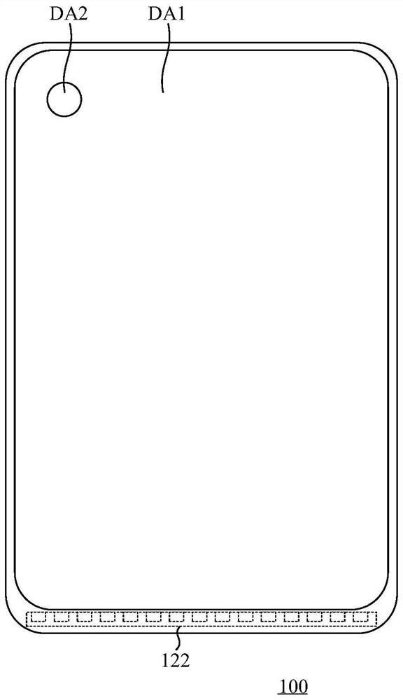
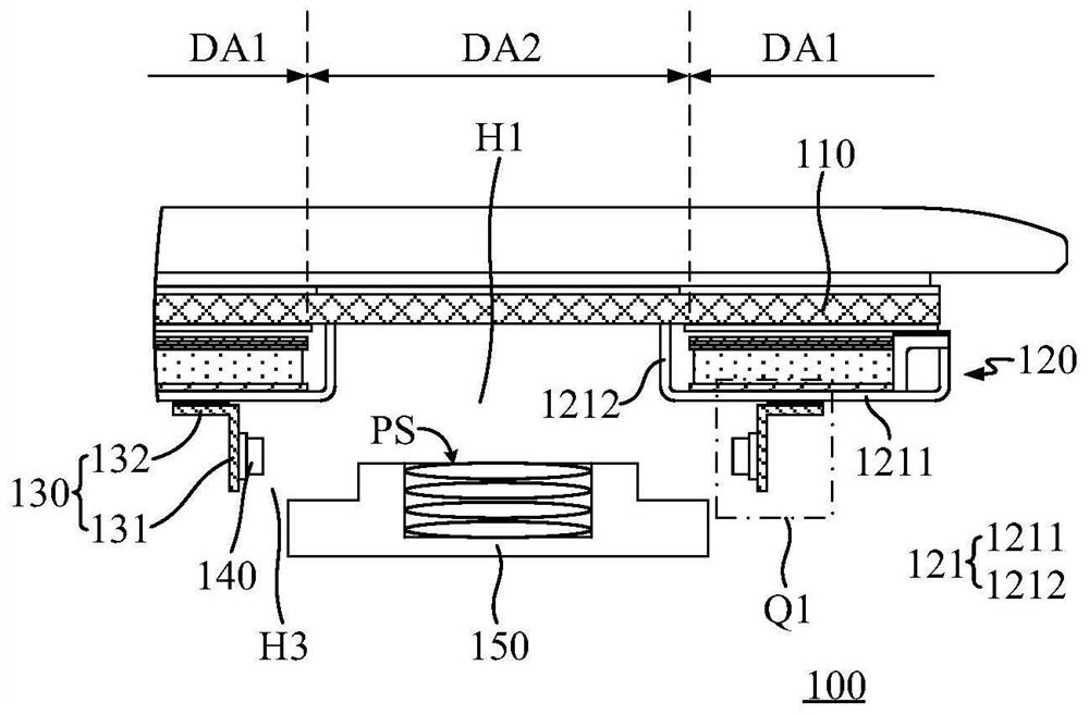
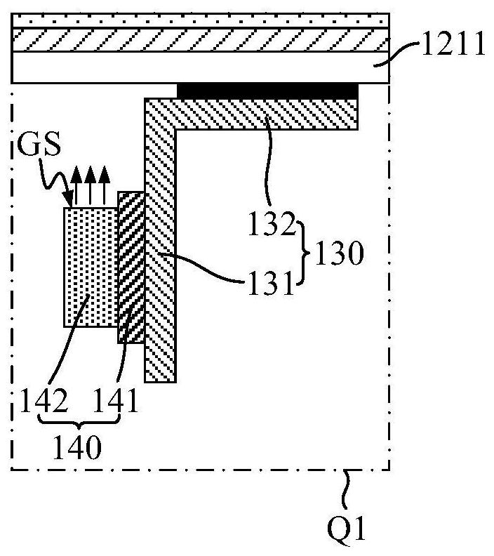
The invention discloses a display device and a control method thereof. The display device comprises a first display area and a second display area; a display panel; and a backlight module which is located on one side of the display panel. The backlight module comprises a bottom frame which comprises a bottom plate comprising a first through hole located in the second display area; a first light source which is mounted on the bottom frame and used for providing backlight for the display panel of the first display area; a sleeve which is connected to the side, deviating from the display panel, of the bottom frame and comprises a barrel-shaped part arranged around the periphery of the first through hole; a second light source which is mounted on the sleeve, used for providing backlight for the display panel of the second display area, and located on the periphery of the first through hole; and a photosensitive element which is located on the side, deviating from the display panel, of thebacklight module, and of which at least part of the photosensitive surface is located in the second display area. According to the display device provided by the embodiment of the invention, the firstdisplay area of the display panel can transmit light and conduct display, so that under-screen integration of the photosensitive element is convenient to realize.

Description

technical field [0001] The present invention relates to the display field, in particular to a display device and a control method thereof. Background technique [0002] Liquid Crystal Display (LCD) panels are widely used in terminal devices such as mobile phones and tablet computers and home appliances such as TVs due to their thin body, soft display screens, no eye damage, and no radiation. [0003] In the current mainstream terminal device design, the front of the terminal device is usually equipped with a display panel and a photosensitive element at the same time. In order to increase the proportion of the display panel of the terminal device, the photosensitive element is integrated with the liquid crystal display panel. In the prior art, when the liquid crystal display panel is integrated with the photosensitive element, holes or grooves need to be formed in the region where the photosensitive element is integrated, and the holed region or the grooved region cannot be ...

Claims


Application Information

Patent Timeline
Patent Type & Authority Applications(China)
IPC IPC(8): G02F1/13357
CPCG02F1/1336G02F1/133608
Inventor 朱志强陈如星柯耀作
Owner XIAMEN TIANMA MICRO ELECTRONICS
Learn More