Rubber track raw material treatment device

A raw material processing and rubber crawler technology, which is applied in the rubber field, can solve the problems of processing and use, inability to carry out rubber mixing treatment, and inability to squeeze and mix rubber at the tip of the wedge block.

Active Publication Date: 2020-12-29
山东珠琳智造股份有限公司
View PDF12 Cites 2 Cited by
  • Summary
  • Abstract
  • Description
  • Claims
  • Application Information

AI Technical Summary

Problems solved by technology

[0005] In order to overcome some factories in the prior art, the raw rubber is first cut into wedge-shaped pieces, and then the wedge-shaped raw rubber is mixed. During the rubber mixing process, the wedge-shaped pieces are manually held, with the pointed end of the wedge-shaped pieces facing the roll gap. , put the raw rubber into the roll gap, and replace the common rectangular block with a wedge block. By using the shape characteristics of the wedge block, the step of pressing the rectangular block into the roll gap can be omitted, but the wedge block also has disadvantages. Ensure that the wedge-shaped raw rubber block is inserted vertically between the roller groups of the rubber mixing equipment, and when the narrow end of the wedge-shaped block is placed downward between the roller groups of the rubber mixing equipment, because there is a certain distance between the roller groups of the rubber mixing equipment, the narrow end It directly passes through the gap of the roller group of the rubber mixing equipment, and the rubber mixing process cannot be performed, so that the tip part of the wedge block cannot be squeezed and mixed. Separating the tip part of the wedge-shaped block that has not been fully mixed for additional secondary mixing, the efficiency is low and the steps are cumbersome. The technical problem to be solved by the present invention is: to provide a rubber crawler raw material processing device

Method used


Image

  • Rubber track raw material treatment device
  • Rubber track raw material treatment device
  • Rubber track raw material treatment device

Examples


Embodiment 1

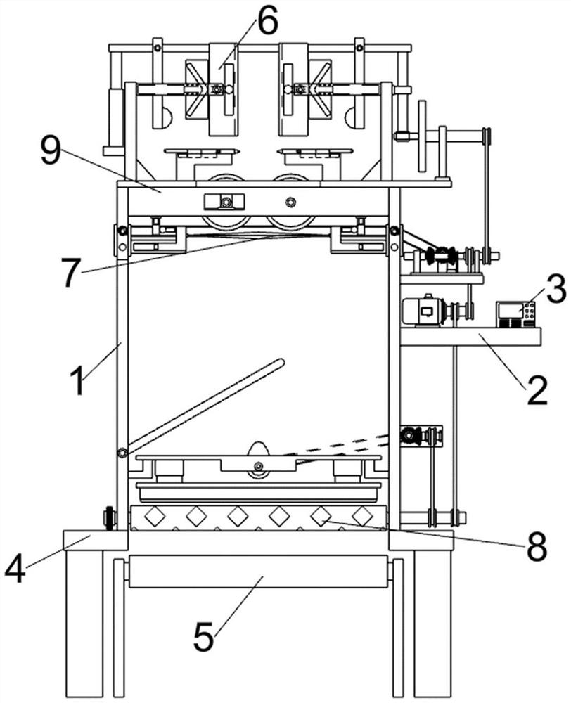
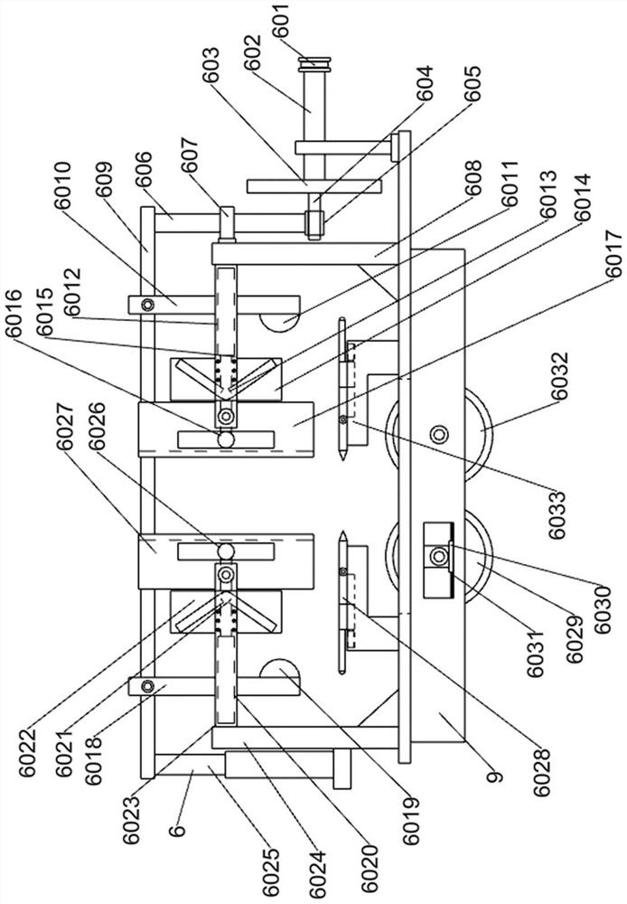
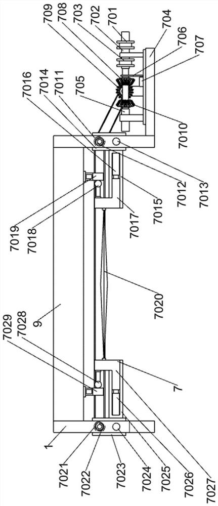
[0025] A rubber crawler raw material processing device, such as Figure 1-6 As shown, it includes separation processing cabin 1, frame connecting plate 2, operation control panel 3, supporting foot platform 4, independent conveyor belt 5, precise feeding mechanism 6, corner separation mechanism 7, refining mechanism 8 and top connection The platform 9; the separation treatment cabin 1 is bolted to the frame connecting plate 2; the bottom of the separation treatment cabin 1 is connected to the supporting foot platform 4; the bottom of the separation treatment cabin 1 is provided with an independent conveyor belt 5; The connecting platen 9 is connected; the operation control panel 3 is arranged above the frame connecting plate 2; the top connecting platen 9 is connected with the precise feeding mechanism 6; the precise feeding mechanism 6 is connected with the corner separation mechanism 7; the separation process The cabin 1 is connected with the corner separation mechanism 7; t...


PUM


Abstract

The invention relates to the field of rubbers, in particular to a rubber track raw material treatment device. The technical purpose to be achieved is to provide the rubber track raw material treatmentdevice. According to the technical scheme, the rubber track raw material treatment device comprises a separation treatment cabin, a rack connecting plate, an operation control screen, a supporting bottom foot table, an independent conveying belt, a precise feeding mechanism, an angle end separation mechanism, a supplementary mixing mechanism and a top connecting table plate. The separation treatment cabin is in bolted connection with the rack connecting plate. A wedge-shaped block raw rubber is limited in an auxiliary mode to accurately enter the position between two rollers of rubber mixingequipment, a wedge-shaped block tip raw rubber which cannot be subjected to rubber mixing treatment due to the fact that the width of the wedge-shaped block tip raw rubber is smaller than the gap between the two rollers of the rubber mixing equipment can be cut and separated from a body, a large raw rubber obtained after rubber mixing is separated, and a tip cutting separation part is subjected tosecondary supplementary mixing treatment.

Description

technical field [0001] The invention relates to the rubber field, in particular to a rubber track raw material processing device. Background technique [0002] Rubber tracks are tracks made of rubber and skeleton materials, which are widely used in construction machinery, agricultural machinery and military equipment. [0003] At present, in the existing technology, some factories first cut the raw rubber into wedge-shaped pieces, and then carry out the rubber mixing process on the wedge-shaped raw rubber. During the rubber mixing process, the wedge-shaped pieces are manually held, with the pointed ends of the wedge-shaped pieces facing the roll gap. , put the raw rubber into the roll gap, and replace the common rectangular block with a wedge block. By using the shape characteristics of the wedge block, the step of pressing the rectangular block into the roll gap can be omitted, but the wedge block also has disadvantages. Ensure that the wedge-shaped raw rubber block is ins...

Claims


Application Information

Patent Timeline
IPC IPC(8): B29B7/56B29B7/60B29B7/58
CPCB29B7/56B29B7/60B29B7/58
Inventor 张占斌
Owner 山东珠琳智造股份有限公司
Why Eureka
Try Eureka