A multi-purpose vehicle mount fixed on the roof
A technology of roof and slanted struts, applied in vehicle components, transportation and packaging, etc., can solve the problems of easy and convenient rest and entertainment, single function and fixing method, and inability to provide for passengers and drivers
- Summary
- Abstract
- Description
- Claims
- Application Information
AI Technical Summary
Problems solved by technology
Method used
Image
Examples
Embodiment 1
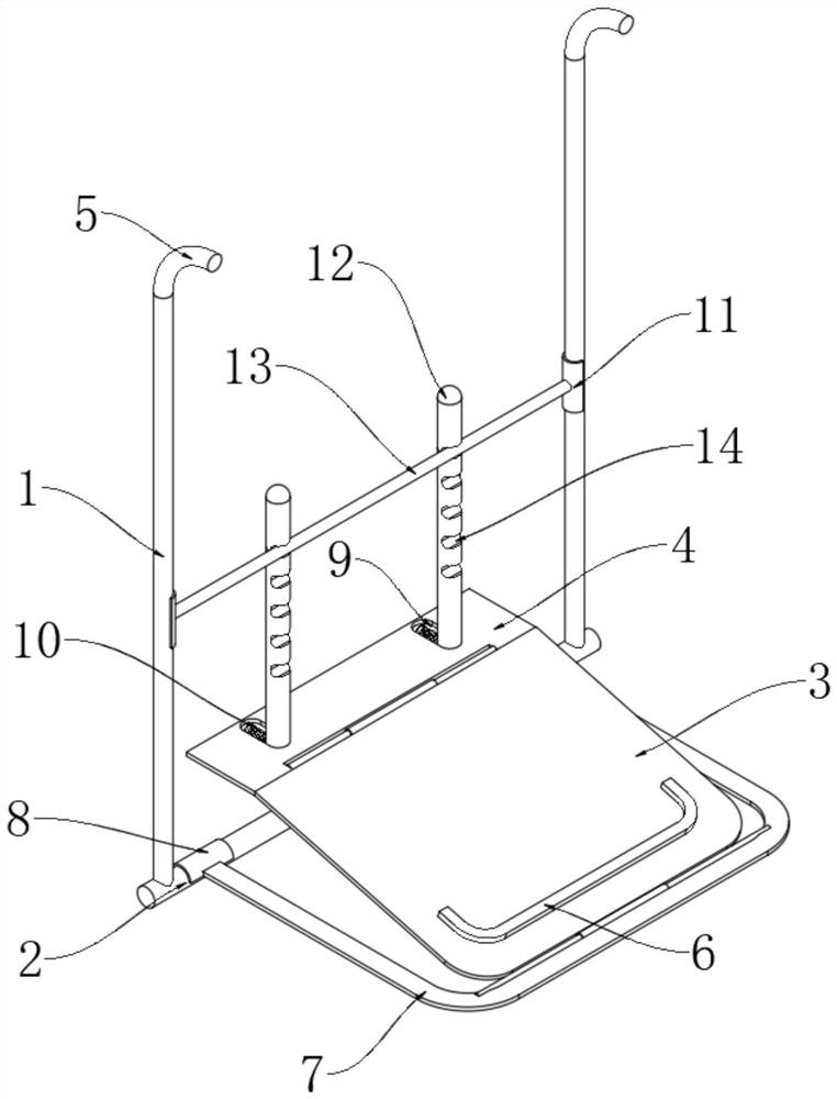
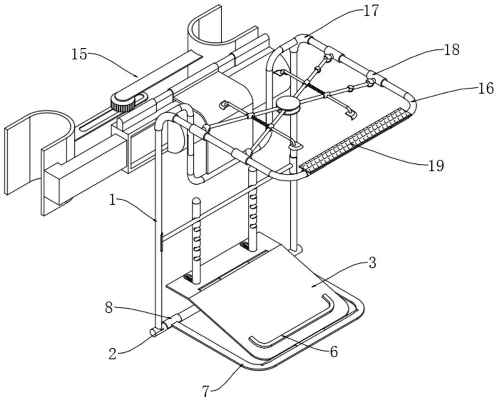
[0036] see Figure 1-2 , a multi-purpose vehicle-mounted bracket fixed on the roof, comprising a first bracket 3, the front end of the first bracket 3 is rotatably connected in the first transverse frame 7 through a rotating shaft, and the rear end of the first bracket 3 is rotatably connected with an adjustment plate 4 through a rotating shaft; Both ends of the same side of the first transverse frame 7 are fixedly connected with a clamping half-ring A8, and the clamping half-ring A8 is movably clamped on the cross strut 2, and the upper sides of the two ends of the cross strut 2 are fixedly connected with a vertical strut 1;
[0037] Two adjusting grooves 9 are provided on the adjusting plate 4, and an adjusting rod 12 is slidably connected in the adjusting groove 9, and one side of the adjusting rod 12 is slidably connected with the adjusting groove 9 through an adjusting spring 10;
[0038] The front side of the adjustment rod 12 is provided with a plurality of clamping gr...
Embodiment 2
[0042] see Figure 3-4 , based on Example 1, the difference is that:
[0043] The upper end of the vertical support rod 1 is movably connected to the connecting pipe 5, and the connecting pipe 5 is fixedly connected to the outside of the connecting pipe sleeve 17, and a U-shaped frame 33 is fixedly connected between the two connecting pipe sleeves 17, and the central upper side of the U-shaped frame 33 is fixedly connected. There is an arc-shaped connecting plate 27, and a U-shaped ferrule 28 is fixedly connected to the rear side of the upper end of the arc-shaped connecting plate 27, and the U-shaped ferrule 28 is movably clamped on the installation mechanism 15.
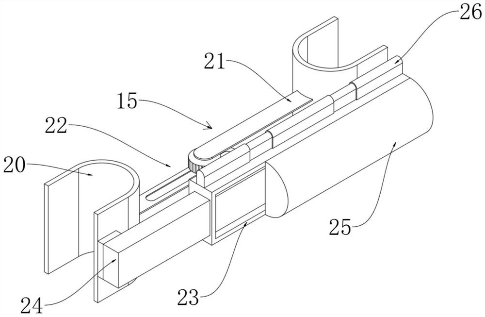
[0044] Mounting mechanism 15 comprises mounting base 26, and U-shaped ferrule 28 is movably clamped on mounting base 26 central upper part, and mounting base 26 lower end is fixedly connected with mounting frame 23; In mounting frame 23, movable insertion is provided with mounting rod 24, and mounting rod 24 is con...
Embodiment 3
[0047] see Figure 5-8 , based on Embodiment 1-2, the difference is that:
[0048] A second transverse frame 16 is fixedly connected between the front sides of the connecting pipes 5 on both sides, and a connecting sleeve 18 is movably connected to the second transverse frame 16; Suction with the roof; connecting bushing 18 is provided with four, wherein two connecting bushings 18 on one side are fixedly connected with the first spherical shell 36, the first spherical shell 36 is movably connected with the first sphere, the first sphere The second spherical shell 37 is fixedly connected through the connecting rod;
[0049] A second sphere 46 is movably connected in the second spherical shell 37, and the second sphere 46 is fixedly connected to the end of the second oblique strut 40; the second oblique strut 40 is all rotatably connected to the inside of one side of the adsorption disc 35, and the adsorption disc The other side of 35 is internally connected with a first obliq...
PUM
 Abstract
Description
Claims
Application Information
 - R&D
- Intellectual Property
- Life Sciences
- Materials
- Tech Scout
- Unparalleled Data Quality
- Higher Quality Content
- 60% Fewer Hallucinations
Browse by: Latest US Patents, China's latest patents, Technical Efficacy Thesaurus, Application Domain, Technology Topic, Popular Technical Reports.
© 2025 PatSnap. All rights reserved.Legal|Privacy policy|Modern Slavery Act Transparency Statement|Sitemap|About US| Contact US: help@patsnap.com


