Automatic winding device for power grid and using method thereof

A wire winding device and power grid technology, which is applied in the direction of transportation and packaging, delivery of filamentous materials, thin material processing, etc., can solve problems such as grid breakage, shortened service life, and grid creases

Active Publication Date: 2020-10-30
徐州鼎诚环保科技有限公司
View PDF9 Cites 7 Cited by
  • Summary
  • Abstract
  • Description
  • Claims
  • Application Information

AI Technical Summary

Problems solved by technology

[0003] At present, when using the power grid, there are permanent installation of the power grid and temporary use of the power grid, and the temporary use of the power grid often requires winding, but the current storage of the power grid still has the following disadvantages: 1. The current storage device does not have protective measures. It is easy to cause the power grid to be weathered and the service life is greatly shortened; 2. When the power grid is rolled up, it is easy to cause creases to the power grid and cause the power grid to break; 3. After the existing power grid is rolled, its weight is relatively heavy. It is inconvenient to move; therefore, to sum up the above-mentioned problems, this technical solution proposes an automatic winding wire device for power grid and its use method, which is used to solve the above-mentioned problems

Method used


Image

  • Automatic winding device for power grid and using method thereof
  • Automatic winding device for power grid and using method thereof
  • Automatic winding device for power grid and using method thereof

Examples


Embodiment 1

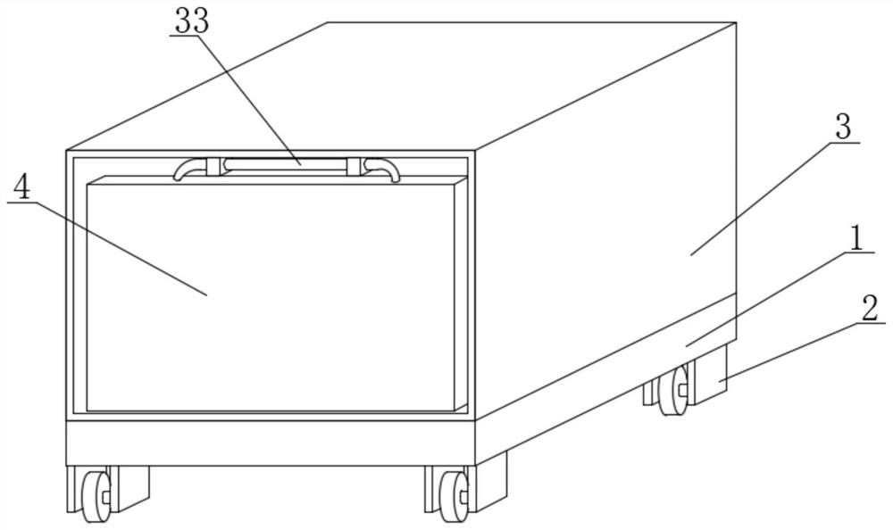
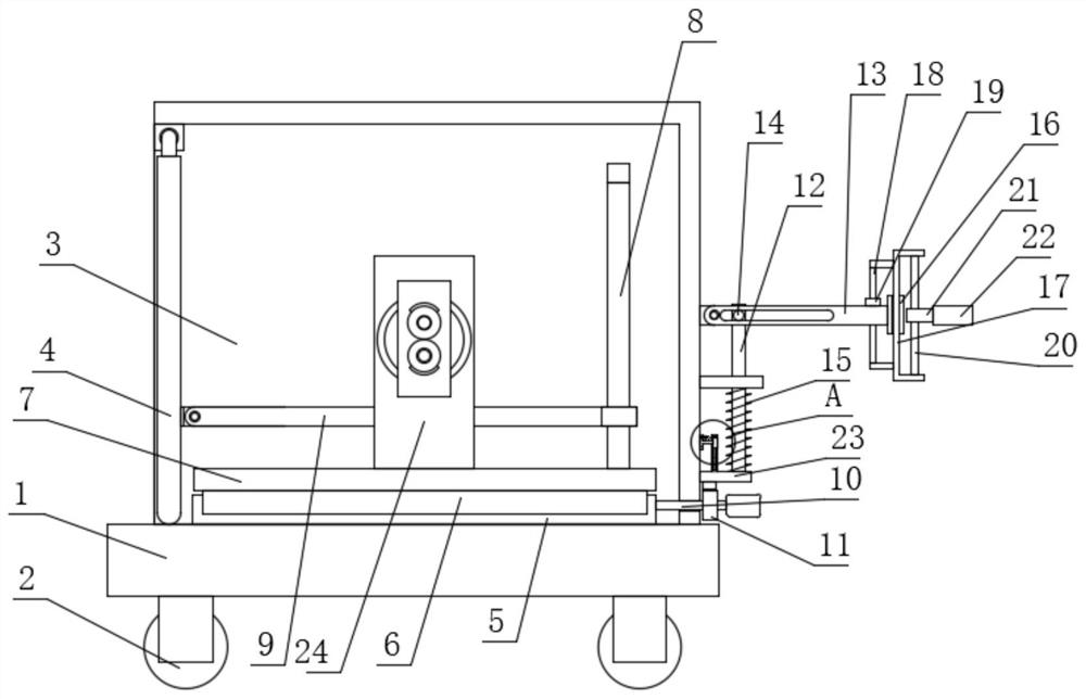
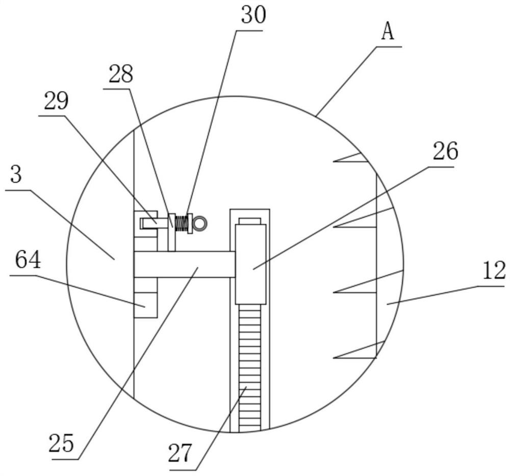
[0047] Embodiment one: if Figure 1-9 As shown, an automatic winding wire device for a power grid includes a base 1, wheels 2 are arranged on the four corners of the bottom of the base 1, and a protective cover 3 with an opening on one side is fixedly installed on the top of the base 1, and the protective cover 3 The inner rotation is connected with the door panel 4, the top of the base 1 is slidably connected with the support plate 7, the top side of the support plate 7 is fixedly installed with a limit frame 8, and the limit frame 8 is slidably connected with a connecting frame 9, and the connecting frame 9 is connected to the door panel. One side of 4 is rotationally connected, one side of protective cover 3 is rotationally connected with support ring 13, and one side of protective cover 3 is slidingly connected with pressure rod 12, and pressure rod 12 is movably clamped with support plate 7, and support ring 13 is connected with The pressure bar 12 is connected by transmi...

Embodiment 2

[0061] Embodiment two: if Figure 10-15 As shown, an automatic winding wire device for power grids, the difference between this embodiment and Embodiment 1 is that: the top of the side of the two fixed plates 24 close to each other is fixed with a ring slide rail 41, and the ring slide rail 41 is A slip ring 42 is slidably connected, and a rotating plate 43 is fixedly installed on the side where the two slip rings 42 are close to each other, and the two rotating plates 43 are respectively fixedly connected to the side where the two limiting plates 44 are far away from each other, and the driving motor 45 The output shaft is fixedly connected to one side of the rotating plate 43 located on one side, and the inner wall of one side of the connecting groove 46 is rotatably connected to a connecting gear 51, and the side of the two moving plates 47 close to each other is fixedly installed with a connecting rack 50, the two connecting racks 50 are meshed with the connecting gear 51,...


PUM


Abstract

The invention discloses an automatic winding device for a power grid and a using method thereof. The automatic winding device comprises a base, wherein wheels are arranged at the four corners of the bottom of the base, a protective cover with an opening formed in one side is fixedly mounted at the top of the base, a door plate is rotationally connected into the protective cover, a supporting plateis slidably connected to the top of the base, a limiting frame is fixedly installed on one side of the top of the supporting plate, a connecting frame is slidably connected to the limiting frame, theconnecting frame is rotatably connected with one side of the door plate, a supporting ring is rotatably connected with one side of the protective cover, a pressing rod is slidably connected with oneside of the protective cover, the pressing rod and the supporting plate are movably clamped, the supporting ring is in transmission connection with the pressing rod, and one side of the supporting ring is in sliding connection with a moving frame. According to the automatic winding device, the power grid can be automatically wound, stored and moved, so that the power grid can be effectively protected, the power grid can be prevented from being damaged, and good use stability and convenience are achieved.

Description

technical field [0001] The invention relates to the technical field of electric power equipment, in particular to an automatic winding wire device for a power grid and a method for using the same. Background technique [0002] The high-voltage pulse grid is an intelligent perimeter system composed of a pulse generator (host) and a front-end fence, and has high-security perimeter protection functions such as anti-theft and alarm. Nowadays, the installation of pulsed power grids in various beast venues in the zoo is a necessary technical precaution to improve safety and improve the viewing effect of tourists. [0003] At present, when using the power grid, there are permanent installation of the power grid and temporary use of the power grid, and the temporary use of the power grid often requires winding, but the current storage of the power grid still has the following disadvantages: 1. The current storage device does not have protective measures. It is easy to cause the pow...

Claims


Application Information

Patent Timeline
Patent Type & Authority Applications(China)
IPC IPC(8): B65H54/553B65H54/28B65H54/72B65H54/70
CPCB65H54/553B65H54/28B65H54/72B65H54/70
Inventor 毛东强
Owner 徐州鼎诚环保科技有限公司
Why Eureka
Try Eureka