Opposite-pull locking mechanism

A technology of locking mechanism and locking hole, which is applied in the direction of mechanical equipment, connecting components, etc., can solve the problems of increasing the peripheral size of the workpiece, the workpiece connection flange with limited workpiece size, etc., and achieve the effect of convenient ejection

Active Publication Date: 2020-12-29
CENTRIX EG
View PDF5 Cites 0 Cited by
  • Summary
  • Abstract
  • Description
  • Claims
  • Application Information

AI Technical Summary

Problems solved by technology

At present, the method often adopted is to set up a mechanism such as a pull bolt to connect, but to use a pull bolt to connect, it is necessary to set up a structure such as a flange or a connecting sleeve, which will lead to the need to form a convex structure on the outer periphery of the connected workpiece. Increasing the peripheral size of the workpiece is not conducive to some situations where the size of the workpiece is limited or the workpiece is too small to form a connecting flange.

Method used


Image

  • Opposite-pull locking mechanism
  • Opposite-pull locking mechanism
  • Opposite-pull locking mechanism

Examples


Embodiment Construction

[0020] The present invention will be further described below in conjunction with the accompanying drawings and specific embodiments.

[0021] It should be noted that if there are directional indications used in the present invention, such as up, down, left, right, front, back, direction and orientation terms, it is to facilitate the description of the relative positional relationship between components, not for related components and components. The absolute position of the positional relationship refers only to explaining the relative positional relationship and movement conditions between the components in a specific posture. If the specific posture changes, the directional indication will also change accordingly. .

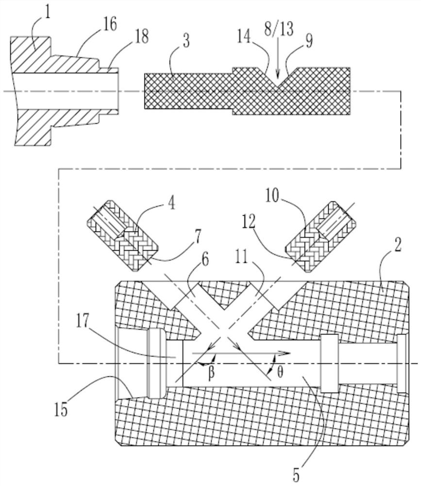
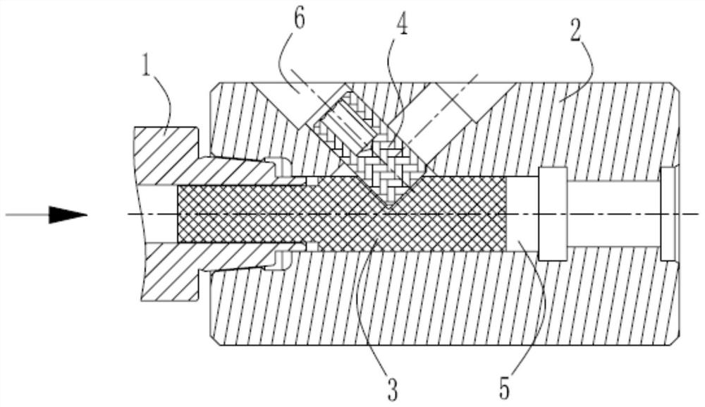
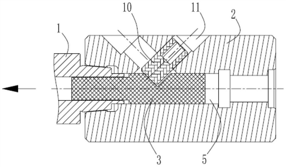
[0022] The double-pull locking mechanism of the present invention includes a first workpiece 1 and a second workpiece 2, and also includes a mandrel 3 and a locking screw 4. A mounting hole 5 is provided in the second workpiece 2, and one end of the mandrel 3 i...


PUM


Abstract

The invention discloses an opposite-pull locking mechanism, belongs to the field of mechanical connecting mechanisms, and provides an opposite-pull locking mechanism capable of realizing opposite-pulllocking connection of two workpieces without increasing the outer contour sizes of the workpieces. The opposite-pull locking mechanism comprises the first workpiece, the second workpiece, and furthercomprises a core rod and a locking screw. A mounting hole is formed in the second workpiece. One end of the core rod is inserted into the mounting hole, and the other end of the core rod is connectedand matched with the first workpiece. A locking hole which is inclined relative to the axial direction of the mounting hole is formed in the second workpiece. The inner end of the locking screw is alocking end capable of extending into the mounting hole. A locking groove is formed in the core rod, and the locking end of the locking screw can extend into the mounting hole and is matched with a locking face in an abutting mode to achieve abutting locking of the core rod. By arranging the core rod and the locking screw, the peripheral sizes of original workpieces are not increased, so that thecorresponding peripheral size of the connected workpieces can be smaller, and the requirements of small parts and some limited installation conditions are met.

Description

technical field [0001] The invention relates to a mechanical connection mechanism for realizing the connection of two workpieces, in particular to a pair-pull locking mechanism. Background technique [0002] At present, for the double-tension connection structure, that is, one of the workpieces and the other workpiece need to form a certain tension relationship strength in the direction of connection to ensure the stability after the connection. At present, the method often adopted is to set up a mechanism such as a pull bolt to connect, but to use a pull bolt connection, it is necessary to set up a convex flange or a connecting sleeve, which will lead to the need to form a convex structure on the outer periphery of the connected workpiece. Increasing the peripheral size of the workpiece is not conducive to some situations where the size of the workpiece is limited or the workpiece is too small to form a connecting flange. Contents of the invention [0003] The technical ...

Claims


Application Information

Patent Timeline
Patent Type & Authority Applications(China)
IPC IPC(8): F16B21/16
CPCF16B21/16
Inventor 张高申绍旭龙港赵庆军李海峡夏科尧
Owner CENTRIX EG
Why Eureka
Try Eureka