Mould for manufacturing special cable

A cable and special-shaped technology, which is applied in the direction of cable/conductor manufacturing, electrical components, circuits, etc., can solve problems such as unsuitable for making cables, unfavorable overhead laying, and large outer diameter of optical cables, achieving high mechanical reliability and reducing processes Quantity, the effect of reducing production cost

Inactive Publication Date: 2013-07-10
STATE GRID CORP OF CHINA +2
View PDF4 Cites 0 Cited by
  • Summary
  • Abstract
  • Description
  • Claims
  • Application Information

AI Technical Summary

Problems solved by technology

[0002] The application of optical cables and electric cables has become increasingly popular. In the prior art, optical cables are usually in a circular structure, and are stranded by a plurality of loose tubes and filling ropes around the strength member located in the center of the optical cable, and then the stranded body is covered with resistance. The water or moisture-proof layer is covered with a sheath layer outside the water-blocking or moisture-proof layer. This kind of optical cable usually has a large outer diameter, which is not conducive to overhead laying; Therefore, it is inconvenient to construct
In the prior art, the above-mentioned problems also exist in cables; the cable molds in the prior art are not suitable for making the cables involved in the present invention

Method used


Image

  • Mould for manufacturing special cable
  • Mould for manufacturing special cable
  • Mould for manufacturing special cable

Examples


Embodiment 1

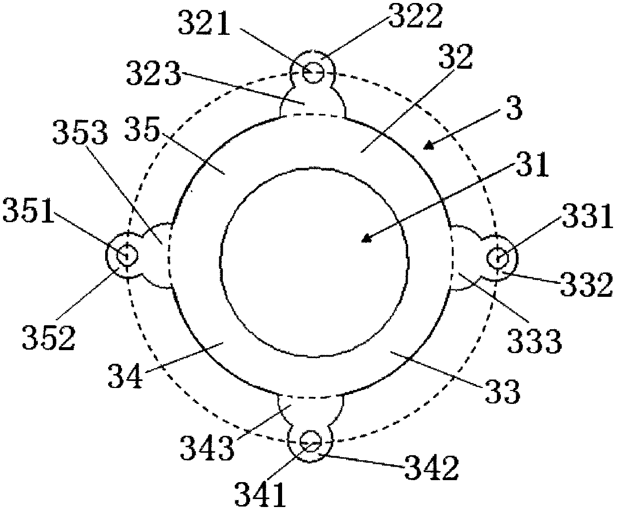
[0048] please see figure 1 and figure 2 , the special-shaped cable 3 is characterized in that it comprises a first special-shaped body, a second special-shaped body, a third special-shaped body, a fourth special-shaped body, a sheath, and a cable core 31; wherein, the first special-shaped body includes: a first reinforced Part 321, the first special-shaped member 322 covering the first reinforcement, the first connecting rib 323 connecting the first special-shaped member and the sheath; the second special-shaped body includes: the second reinforcement 331, covering the second reinforcement The second special-shaped member 332 of the piece, the second connecting rib 333 connecting the second special-shaped member and the sheath; the third special-shaped body includes: the third reinforcement 341, the third special-shaped member 342 covering the third reinforcement, connecting The third connecting rib 343 between the third special-shaped member and the sheath; the fourth spec...

Embodiment 2

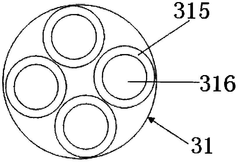
[0052] please see figure 1 and image 3 , special-shaped cable 3, basically the same as the implementation example 1, the difference is that: the cable core is composed of a plurality of insulated wires, the insulated wires are parallel to each other or twisted with each other, and each insulated wire is composed of an inner conductor 316 and a wrapped An insulating layer 315 covering the conductor is formed.

Embodiment 3

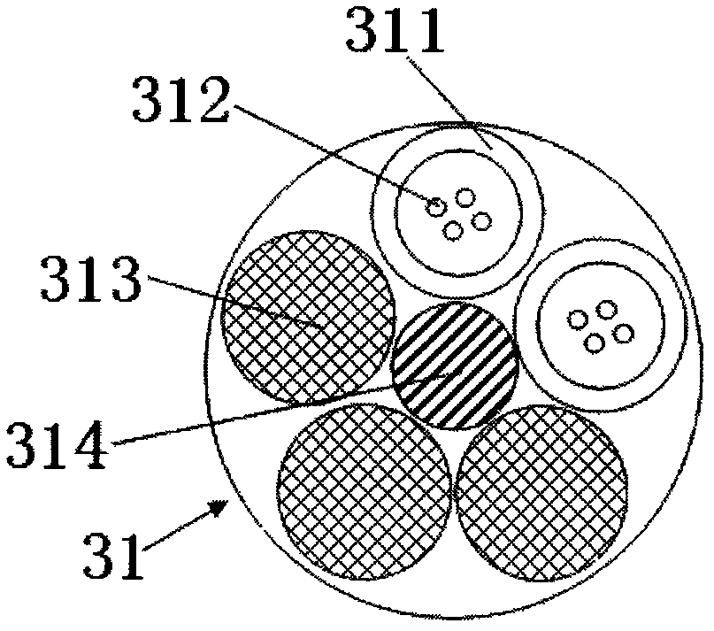
[0054] please see figure 1 and Figure 4 , and refer to figure 2 and image 3 , special-shaped cable 3, which is basically the same as the implementation example 1, except that the cable core is composed of a central strengthening member 314 at the center, a plurality of protective tubes 311 twisted around the central strengthening member, at least two insulated wires and The protective tube is composed of a filling rope 313, and the protective tube has at least one optical fiber 312; the insulated wire is composed of a conductor 316 inside and an insulating layer 315 covering the conductor.


PUM

PropertyMeasurementUnit
densityaaaaaaaaaa
tensile strengthaaaaaaaaaa
dielectric strengthaaaaaaaaaa

Abstract

The invention belongs to the technical field of cables and particularly relates to a mould for manufacturing a special cable. The mould comprises a mould cover part and a mould core part, and is characterized in that the mould cover part is composed of a mould cover rear end body and a mould cover front end body; and the mould core part comprises a first mould core part, a second mould core part and a third mould core part which are sequentially connected. The mould provided by the invention has the advantages of simple structure, easiness for manufacturing, easiness for installation and debugging, high product qualification rate of produced cables, easiness for cable laying and the like.

Description

technical field [0001] The invention belongs to the technical field of cables, in particular to a mold for manufacturing special-shaped cables. Background technique [0002] The application of optical cables and electric cables has become increasingly popular. In the prior art, optical cables are usually in a circular structure, and are stranded by a plurality of loose tubes and filling ropes around the strength member located in the center of the optical cable, and then the stranded body is covered with resistance. The water or moisture-proof layer is covered with a sheath layer outside the water-blocking or moisture-proof layer. This kind of optical fiber cable usually has a large outer diameter, which is not conducive to overhead laying; Therefore, construction is inconvenient. In the prior art, the above-mentioned problems also exist in cables; the cable molds in the prior art are not suitable for making the cables involved in the present invention. Contents of the in...

Claims


Application Information

Patent Timeline
Patent Type & Authority Patents(China)
IPC IPC(8): H01B13/00H01B13/24G02B6/44
Inventor 施文杜
Owner STATE GRID CORP OF CHINA
Why Eureka
Try Eureka