Data transmission method, terminal and communication system
A data transmission and terminal technology, applied in the field of communication, can solve problems such as poor application data transmission effect and inability to meet transmission requirements, and achieve the effect of meeting the needs of service quality
Active Publication Date: 2020-12-29
HUAWEI TECH CO LTD
6 Cites 0 Cited by
AI-Extracted Technical Summary
Problems solved by technology
[0004] At present, the multi-path transmission of data generated by the application from the source terminal to the dest...
Method used
[0060] The embodiment of the present application provides a data transmission method. The terminal can determine the transmission path for transmitting application data based on the quality of service (QoS) information of each transmission path, thereby meeting the quality of service requirements of data transmission. The embodiment of the present application also provides a corresponding terminal, a communication system, and a storage medium. Each will be described in detail below.
[0067] In the communication system provided by the embodiment of the present application, the terminal can determine the transmission path used to transmit the data generated by the application based on the quality of service (QoS) information of each transmissi...
Abstract
The invention discloses a data transmission method. The method comprises the following steps that: a first terminal acquires first data to be transmitted to a second terminal, the first data are generated by a first application, the QoS information of each transmission path in N available transmission paths is acquired, and N is an integer greater than 1; the N available transmission paths are communication paths between the first terminal and the second terminal, and then the first terminal determines a first transmission path of which the QoS information satisfies a transmission condition from the N transmission paths; and the first terminal transmits the first data through the first transmission path. According to the scheme provided by the embodiment of the invention, the terminal candetermine the transmission path for transmitting the data generated by the application based on the QoS information of each transmission path, so that the requirement of data transmission on the QoS is met.
Application Domain
Error preventionData switching networks
Technology Topic
Data transmissionQos quality of service +3
Image
Examples
- Experimental program(1)
Example Embodiment
[0058]The following describes the embodiments of the present application with reference to the accompanying drawings. Obviously, the described embodiments are only a part of the embodiments of the present application, rather than all the embodiments. Those of ordinary skill in the art know that with the development of technology and the emergence of new scenarios, the technical solutions provided in the embodiments of the present application are equally applicable to similar technical problems.
[0059]The terms "first" and "second" in the description and claims of the application and the above-mentioned drawings are used to distinguish similar objects, and not necessarily used to describe a specific sequence or sequence. It should be understood that the data used in this way can be interchanged under appropriate circumstances so that the embodiments described herein can be implemented in an order other than the content illustrated or described herein. In addition, the terms "including" and "having" and any variations of them are intended to cover non-exclusive inclusions. For example, a process, method, system, product or device that includes a series of steps or units is not necessarily limited to the clearly listed Those steps or units may include other steps or units that are not clearly listed or are inherent to these processes, methods, products, or equipment.
[0060]The embodiment of the present application provides a data transmission method. A terminal can determine a transmission path for transmitting application data based on the quality of service QoS information of each transmission path, thereby meeting the quality of service requirements for data transmission. The embodiments of the present application also provide corresponding terminals, communication systems, and storage media. Detailed descriptions are given below.
[0061]A terminal (also known as user equipment (UE)) is a device with wireless transceiver functions, which can be deployed on land, including indoor or outdoor, handheld or vehicle-mounted; or on the water (such as ships, etc.) ); It can also be deployed in the air (for example, on airplanes, balloons, and satellites). The terminal may be a mobile phone, a pad, a computer with wireless transceiver function, a virtual reality (VR) terminal, an augmented reality (AR) terminal, an industrial control (industrial control) Wireless terminals in, self-driving (self driving), wireless terminals in remote medical, wireless terminals in smart grid, wireless terminals in transportation safety, Wireless terminals in smart cities, wireless terminals in smart homes, etc.
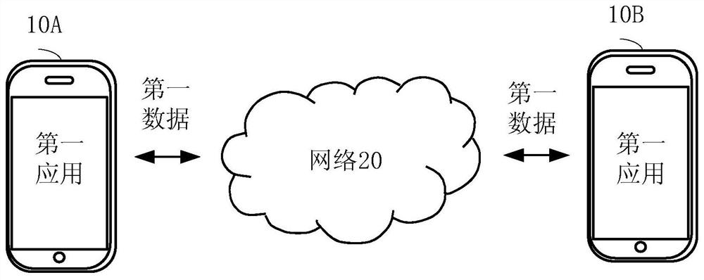
[0062]figure 1 This is a schematic diagram of an embodiment of a communication system provided in an embodiment of this application.
[0063]Such asfigure 1 As shown, an embodiment of the communication system provided by the embodiment of the present application may include a first terminal 10A, a second terminal 10B, and a network 20. The first terminal 10A and the second terminal 10B communicate through the network 20. The network 20 may include multiple routing devices.
[0064]The first terminal 10A obtains first data to be transmitted to the second terminal 10B, the first data being generated by the first application. The first terminal obtains quality of service (QoS) information of each transmission path in N available transmission paths, where N is an integer greater than 1, and the N available transmission paths are between the first terminal and the The communication path between the second terminals; the first terminal determines from the N transmission paths a first transmission path whose QoS information satisfies the transmission condition; the first terminal transmits the data through the first transmission path The first data.
[0065]The second terminal uses 10B to receive the first data from the first transmission path; and schedule the first data to the first application.
[0066]It should be noted that thefigure 1 The first terminal 10A and the second terminal 10B are both mobile phones as examples. In fact, in different scenarios, the first terminal 10A and the second terminal 10B are not limited to mobile phones, and the first terminal 10A and the second terminal 10B are also It can be different terminal devices.
[0067]In the communication system provided by the embodiment of the present application, the terminal can determine the transmission path for transmitting the data generated by the application based on the quality of service QoS information of each transmission path, thereby meeting the quality of service requirement for data transmission.
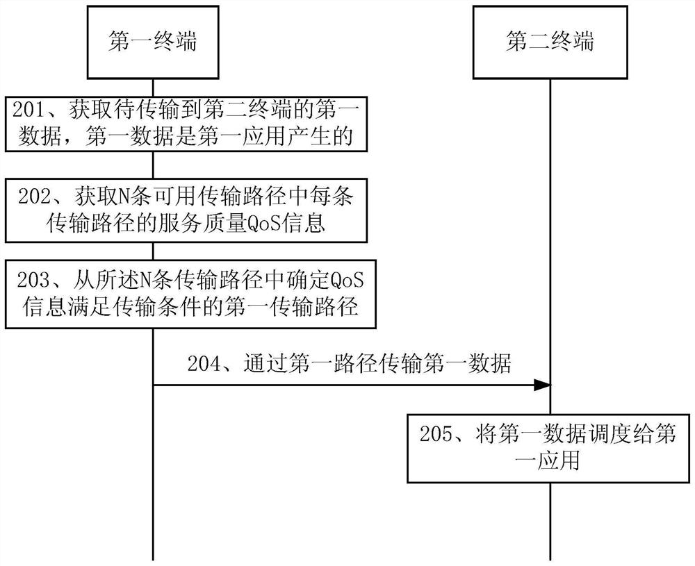
[0068]The foregoing describes the communication system provided by the embodiments of the present application, and the following is combinedfigure 2 Introduce the data transmission method provided in the embodiment of this application.
[0069]Such asfigure 2 As shown, an embodiment of the data transmission method provided in the embodiment of the present application may include:
[0070]201. A first terminal acquires first data to be transmitted to a second terminal, where the first data is generated by a first application.
[0071]202. The first terminal obtains the quality of service QoS information of each of the N available transmission paths.
[0072]The N is an integer greater than 1, and the N available transmission paths are communication paths between the first terminal and the second terminal.
[0073]QoS information may include information such as transmission bandwidth, transmission delay, packet loss rate, and jitter.
[0074]There may be multiple available transmission paths between the first terminal and the second terminal, and each available transmission path may be generated through negotiation between the first terminal and the second terminal, or may be an intermediate connection between the first terminal and the second terminal. Negotiation generated by the control device.
[0075]In some possible embodiments, step 202 may include:
[0076]The first terminal determines N QoS flows, where each QoS flow corresponds to an available transmission path;
[0077]The first terminal measures the QoS information of each transmission path among the N available transmission paths corresponding to the N QoS flows through a measurement message.
[0078]In the embodiment of this application, the QoS flow may be a triplet, a quadruple or a quintuple. If the QoS flow is a triplet, it includes a source Internet protocol (IP) address, an IP protocol, and a destination IP address. If the QoS flow is a four-tuple, it includes the source IP address, source port number, destination IP address and destination port number. If the QoS flow is a 5-tuple, it includes the source IP address, source port number, IP protocol, destination IP address, and destination port number.
[0079]Taking the QoS flow as a four-tuple as an example, each four-tuple corresponds to an available transmission path.
[0080]When measuring available transmission paths, a measurement message may be sent to each available transmission path, and then a response message corresponding to the measurement message may be received, and then the QoS information on the available transmission path may be calculated. For example, the transmission delay can be counted according to the sending time of the measurement message and the receiving time of the response message, and the packet loss rate can be determined according to the number of sent measurement messages and the number of received measurement messages fed back by the destination terminal. Of course, this section is only an example, and other solutions that can determine QoS information are applicable to this application.
[0081]203. The first terminal determines from the N transmission paths the first transmission path whose QoS information meets the transmission condition.
[0082]There can be multiple transmission conditions, such as: the best quality of service is used as the transmission condition, the first X of the service quality is used as the transmission condition, X is an integer greater than 1, and the best dimension of the service quality is used as the transmission condition , Or take one or more dimensions up to a certain threshold as the transmission condition. The transmission condition can be configured according to actual needs, and is not limited to the ones listed here.
[0083]204. The first terminal transmits the first data through the first transmission path.
[0084]205. After receiving the first data, the second terminal schedules the first data to the first application.
[0085]In the data transmission method provided in the embodiments of the present application, the terminal can determine the transmission path for transmitting data generated by the application based on the quality of service QoS information of each transmission path, thereby meeting the quality of service requirements for data transmission.
[0086]In the abovefigure 1 withfigure 2 In the illustrated embodiment, the first terminal 10A is used as the data transmitting end and the second terminal 10B is used as the data receiving end for description. In the actual data transmission process, the first terminal 10A may sometimes be the data sending end and sometimes the data receiving end. Similarly, the second terminal 10B may also be the data receiving end and sometimes the data sending end.
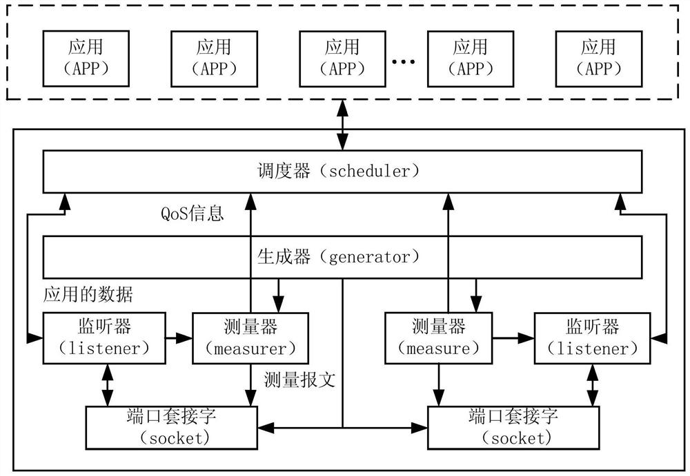
[0087]Whether it is the first terminal 10A or the second terminal 10B, the functions of the terminals involved in the data transmission process of this application can be referred toimage 3 An example schematic diagram is shown for understanding.
[0088]Such asimage 3 As shown, the terminal may include multiple applications (APP), scheduler (scheduler), generator (generator), listener (listener), measurer (measurer) and port socket (socket).
[0089]It should be noted that the scheduler, generator, listener, measurer, and port socket described here can be implemented by software.
[0090]Wherein, each application generates application data, the above-mentioned first application is one of multiple applications, and the first data is data generated by the first application.
[0091]The determination of N QoS flows described in step 202 can be completed by a generator, which is used to negotiate the available IP addresses and ports at both ends of the communication. Of course, it is also possible to generate QoS through pre-configured IP addresses and ports without negotiation Flow, that is, determine the available transmission path.
[0092]Taking the generator to generate quadruples as an example, each quadruple corresponds to a port socket (socket).
[0093]The measurer can be used to measure the QoS information of each of the N available transmission paths. The measurement principle of the measurer can be understood by referring to the corresponding description of measuring QoS information through a message in step 202. After measuring the QoS information of each transmission path, the measurer will report the QoS information of each transmission path to the scheduler. The measurer can send measurement messages through a port socket.
[0094]The scheduler can be used to perform the above step 203, that is, it can determine a suitable transmission path for the data generated by the application according to the QoS information reported by the measurer, and schedule the data of the application to the transmission path. In addition, the scheduler can also distribute the received application data to corresponding applications.
[0095]The listener can be used to receive flow measurement messages and data messages from a port socket (socket), where the data messages refer to application data. After the listener receives the measurement message, measurement response or application data, it will first identify it and then transmit it. After the listener receives the measurement message or measurement response, it will pass the measurement message or measurement response to the measurer, so that the measurer can determine the QoS information of each transmission path. After the listener receives the data of the application, it will pass the data of the application to the scheduler, and then distribute it to the corresponding application through the scheduler. In addition, the listener can also pass the message to be sent to the port socket for message transmission.
[0096]based onimage 3 In the example shown, the process of transmitting application data between the first terminal and the second terminal can participate inFigure 4 Understand.
[0097]Such asFigure 4 As shown, there can be multiple available transmission paths between the first terminal and the second terminal, such asFigure 4 The generator of the first terminal and the generator of the second terminal negotiated two available transmission paths, namely the available transmission path 1 formed by the first terminal via the router A in the network and the second terminal, and the first terminal via the network Available transmission path 2 formed by router B and the second terminal in.
[0098]The measurer 1 on the first terminal measured the available transmission path 2 through the measurement message, and the measurer 2 on the first terminal measured the available transmission path 1 through the measurement message, and measured the available transmission path 1 and the available transmission. The QoS information of path 2 is reported to the scheduler, and the QoS information of available transmission path 2 is better than that of available transmission path 1.
[0099]After the first application transmission of the first terminal generates the first data, the scheduler selects the available transmission path 2 according to the QoS information of the available transmission path 1 and the available transmission path 2 to transmit the first data. After the second terminal receives the first data, the scheduler of the second terminal schedules the first data to the first application.
[0100]In this scenario, a path with good service quality can be selected from the available transmission paths to transmit application data, which can improve the success rate and transmission efficiency of data transmission.
[0101]In some possible embodiments, the determining, by the first terminal from the N transmission paths, the first transmission path whose QoS information satisfies a transmission condition may include:
[0102]Determining, by the first terminal, data transmission of the first application for service quality requirement information in a first dimension, where the service quality includes a first dimension and a second dimension;
[0103]The first terminal determines the transmission path with the highest conformity in the first dimension from the N transmission paths according to the demand information in the first dimension and the QoS information of each transmission path As the first transmission path.
[0104]In the embodiments of this application, it is considered that some applications have relatively high requirements for transmission delay, such as navigation applications and instant messaging applications. Some applications have higher requirements for jitter, such as voice applications and video applications. Some applications require relatively high packet loss rates, such as applications related to precise control. Transmission delay, jitter, and packet loss rate belong to different dimensions of QoS information. In this way, when transmitting data for different applications, you can select a suitable transmission path according to the requirements of various applications for different dimensions of QoS information. For example, there are three available transmission paths, of which the transmission delay of available transmission path 1 is the lowest. , The available transmission path 2 has the lowest jitter, and the available transmission path 3 has the lowest packet loss rate. In this way, when selecting a transmission path for a navigation application, transmission path 1 is selected from the three available transmission paths, and transmission path 1 is used to transmit the data of the navigation application.
[0105]In this scenario, such asFigure 5 As shown, the first application is a navigation application that requires relatively high transmission delay, and the second application is a video application that requires relatively high jitter. The jitter parameter value of the available transmission path 1 is less than the jitter parameter value of the available transmission path 2, and the transmission delay of the available transmission path 2 is less than the transmission delay of the available transmission path 1. After the first application on the first terminal generates data, the scheduler of the first terminal uses the first application’s demand information on transmission delay and the quality of service information in each dimension corresponding to the available transmission path 1 and the available transmission path 2, The data determined to be the first application selects the available transmission path 2 for data transmission. After receiving the data of the first application from the available transmission path 2, the second terminal will schedule the data of the first application to the first application. After the second application on the first terminal generates data, the scheduler of the first terminal determines the quality of service information in each dimension corresponding to the available transmission path 1 and the available transmission path 2 according to the jitter demand information of the second application Select the available transmission path 1 for the data of the second application for data transmission.
[0106]In some possible embodiments, the method may further include:
[0107]The first terminal receives the confirmation information sent by the second terminal through the second transmission path that the first data has been received, and the difference between the QoS information of the second transmission path and the QoS information of the first transmission path The offset is within the preset range.
[0108]In the embodiment of the present application, in order to prevent the data sending end from retransmitting data due to the delay in receiving the ACK message, the data receiving end also selects a transmission path with the best possible QoS to return an ACK message to the data sending end.
[0109]Such asFigure 6 As shown in the scenario, the QoS information of the available transmission path 1 and the available transmission path 2 are the best two transmission paths among the multiple available transmission paths. The first terminal transmits the first data through the available transmission path 2, and the second terminal can The response of the first data is transmitted through the available transmission path 1. In this way, it can be ensured that the first terminal can receive the response of the second terminal in time, thereby avoiding repeated data transmission due to the delay in receiving the response message by the data sender, and wasting transmission resources.
[0110]In some possible embodiments, the method may further include:
[0111]When the first transmission path fails, the first terminal schedules the first data transmitted on the first transmission path to a third transmission path, and the QoS information of the third transmission path is the N available A transmission path with the best service quality among the transmission paths except for the first transmission path.
[0112]In the embodiment of the present application, when the transmission path fails, data migration is performed, and the best transmission path is selected from the remaining available transmission paths for transferring the migrated data during data migration.
[0113]Such asFigure 7 As shown in the scenario, the QoS information of the available transmission path 1 and the available transmission path 2 are the best two transmission paths among the multiple available transmission paths. When the first terminal transmits the first data of the first application through the available transmission path 2 If the available transmission path 2 fails, the scheduler of the first terminal can schedule the first data of the first application to be transmitted on the available transmission path 1.
[0114]In some possible embodiments, the method may further include:
[0115]The first terminal encapsulates a user datagram protocol (user datagram protocol, UDP) tunnel header in the first data;
[0116]The transmitting, by the first terminal, the first data through the first transmission path may include:
[0117]The first terminal transmits the first data encapsulated with the UDP tunnel header through the first transmission path.
[0118]In the embodiment of the present application, the upper-layer application may not be aware of the transmission of data, and may transmit the first data in a tunnel mode, and it is sufficient to encapsulate the UDP tunnel header in the data to be transmitted in the tunnel mode. Such asFigure 8 As shown, before the existing IP, UDP/Transmission Control Protocol (TCP) and data (DATA) formats of the first data, the IP and UDP tunnel headers related to the UDP tunnel are encapsulated so that they can pass The first data is transmitted in a UDP tunnel.
[0119]In some possible embodiments, the method may further include:
[0120]The first terminal receives second data, where the second data includes identification information of the first application;
[0121]The first terminal schedules the second data to the first application according to the identification information of the first application.
[0122]In the embodiment of this application, the upper-layer application can also cooperate to realize data transmission. In this case, each application has a unique APP ID. When sending data, the APP ID is written into the data, and the data receiving device After receiving the data, the APP ID can be parsed to dispatch the second data to the corresponding application. Such asPicture 9 As shown, the application identifier (APP ID) is added to the format of the first data, so that after the first terminal receives the second data, it can determine which application the second data corresponds to through the APP ID, thereby The second data is dispatched to the corresponding application.
[0123]In some possible embodiments, the first terminal acquiring the first data to be transmitted to the second terminal may include:
[0124]The first terminal obtains the first data by running an instance of the first application, where the first application is one of M applications, and each application runs based on a different instance, and the M is an integer , And M≥1.
[0125]In the embodiments of the present application, each application can also be run using one instance, that is, there may be multiple instances, and each instance only serves one application. In this implementation, only the message is scheduled to QoS when sending data. The best transmission path can be used.
[0126]The data transmission method and the corresponding communication system are described above, and the terminal in the embodiment of the present application is described below with reference to the accompanying drawings.
[0127]Such asPicture 10 As shown, an embodiment of the terminal 30 provided in the embodiment of the present application may include:
[0128]The processing unit 301 is configured to obtain the first data to be transmitted to the second terminal, obtain the quality of service QoS information of each of the N available transmission paths, and determine from the N transmission paths that the QoS information meets the transmission conditions The first transmission path, the first data is generated by the first application, the N is an integer greater than 1, and the N available transmission paths are the communication paths between the first terminal and the second terminal ;
[0129]The transceiver unit 302 is configured to transmit the first data through the first transmission path determined by the processing unit 301.
[0130]The embodiment of the present application provides a solution. The terminal can determine a transmission path for transmitting data generated by the application based on the quality of service QoS information of each transmission path, thereby meeting the quality of service requirements for data transmission.
[0131]In some possible embodiments, the processing unit 301 is specifically configured to:
[0132]Determine N QoS flows, where each QoS flow corresponds to an available transmission path;
[0133]Measure the QoS information of each transmission path in the N available transmission paths corresponding to the N QoS flows through the measurement message.
[0134]In some possible embodiments, the processing unit 301 is specifically configured to:
[0135]Determining the demand information of the data transmission of the first application on the quality of service in the first dimension, where the quality of service includes the first dimension and the second dimension;
[0136]According to the demand information in the first dimension and the QoS information of each transmission path, the transmission path with the highest conformity in the first dimension is determined from the N transmission paths as the first Transmission path.
[0137]In some possible embodiments, the transceiver unit 302 is further configured to receive, through a second transmission path, the confirmation information that the first data sent by the second terminal has been received, and the QoS information of the second transmission path and the The offset of the QoS information of the first transmission path is within a preset range.
[0138]In some possible embodiments, the processing unit 301 is further configured to schedule the first data transmitted on the first transmission path to a third transmission path when the first transmission path fails, and the third transmission path The QoS information is the transmission path with the best service quality among the N available transmission paths except for the first transmission path.
[0139]In some possible embodiments, the processing unit 301 is further configured to encapsulate a user datagram protocol UDP tunnel header in the first data;
[0140]The transceiver unit 302 is further configured to transmit the first data encapsulated with the UDP tunnel header through the first transmission path.
[0141]In some possible embodiments, the transceiver unit 302 is further configured to receive second data, where the second data includes identification information of the first application;
[0142]The processing unit 301 is further configured to schedule the second data to the first application according to the identification information of the first application.
[0143]In some possible embodiments, the processing unit 301 is specifically configured to obtain the first data by running an instance of the first application. The first application is one of M applications, and each application is based on a different In the example of running, the M is an integer, and M≥1.
[0144]It should be noted that, because the terminal described above is based on the same concept as the method embodiment of this application, its technical effects are the same as those of the method embodiment of this application. For details, please refer to the above-mentioned method embodiment of this application. The description is not repeated here.
[0145]An embodiment of the present application further provides a computer storage medium, wherein the computer storage medium stores a program, and the program executes some or all of the steps recorded in the above method embodiments.
[0146]Such asPicture 11As shown, this is a schematic structural diagram of another communication device according to an embodiment of the application. The communication device may be a terminal or other devices that can implement the functions of the application. The communication device may include: a processor 401 (for example, a CPU), a memory 402, a transmitter 404, and a receiver 403; the transmitter 404 and the receiver 403 are coupled to the processor 401, and the processor 401 controls the sending and receiving of the transmitter 404 The receiving action of the device 403. The memory 402 may include a high-speed RAM memory, or may also include a non-volatile memory NVM, such as at least one disk memory. The memory 402 may store various instructions for completing various processing functions and implementing the methods of the embodiments of the present application. step. Optionally, the communication device involved in the embodiment of the present application may further include: one or more of a power supply 405 and a communication port 406,Picture 11The devices described in the above may be connected through a communication bus or through other connection methods, which is not limited in the embodiment of the present application. The receiver 403 and the transmitter 404 may be integrated in the transceiver of the communication device, or may be independent receiving and transmitting antennas on the communication device. The communication bus is used to realize the communication connection between the components. The aforementioned communication port 406 is used to implement connection and communication between the communication device and other peripherals.
[0147]In some embodiments, the processor 401 in the communication device can executePicture 10 The action executed by the processing module 301 in the communication device can be executed by the receiver 403 in the communication devicePicture 10 The implementation principles and technical effects of the actions performed by the transceiver unit 302 are similar and will not be repeated here.
[0148]In some embodiments, the aforementioned memory 402 is used to store computer-executable program codes, and the program codes include instructions; when the processor 401 executes the instructions, the instructions cause the processor 401 to perform the actions performed by the processing module of the communication device in the aforementioned embodiments, The transmitter 404 is made to execute the actions of the transceiver unit 302 of the communication device in the foregoing embodiment. The implementation principles and technical effects are similar, and will not be repeated here.
[0149]The present application also provides a chip system that includes a processor for supporting the above-mentioned communication device to realize its related functions, for example, receiving or processing the data and/or information involved in the above-mentioned method embodiment. In a possible design, the chip system further includes a memory, and the memory is used to store necessary program instructions and data of the computer equipment. The chip system can be composed of chips, or include chips and other discrete devices.
[0150]In the above-mentioned embodiments, it may be implemented in whole or in part by software, hardware, firmware, or any combination thereof. When implemented by software, it can be implemented in the form of a computer program product in whole or in part.
[0151]The computer program product includes one or more computer instructions. When the computer program instructions are loaded and executed on the computer, all or part of the processes or functions described in the embodiments of the present application are generated. The computer may be a general-purpose computer, a dedicated computer, a computer network, or other programmable devices. The computer instructions may be stored in a computer-readable storage medium or transmitted from one computer-readable storage medium to another computer-readable storage medium. For example, the computer instructions may be transmitted from a website, computer, server, or data center. Transmission to another website, computer, server, or data center via wired (such as coaxial cable, optical fiber, Digital Subscriber Line (DSL)) or wireless (such as infrared, wireless, microwave, etc.). The computer-readable storage medium may be any available medium that can be stored by a computer or a data storage device such as a server or data center integrated with one or more available media. The usable medium may be a magnetic medium (for example, a floppy disk, a hard disk, a magnetic tape), an optical medium (for example, a DVD), or a semiconductor medium (for example, a solid state disk (SSD)).
[0152]Those skilled in the art can clearly understand that, for the convenience and conciseness of the description, the specific working process of the system, device and unit described above can refer to the corresponding process in the foregoing method embodiment, which will not be repeated here.
[0153]In the several embodiments provided in this application, it should be understood that the disclosed system, device, and method may be implemented in other ways. For example, the device embodiments described above are merely illustrative. For example, the division of the units is only a logical function division, and there may be other divisions in actual implementation, for example, multiple units or components may be combined or It can be integrated into another system, or some features can be ignored or not implemented. In addition, the displayed or discussed mutual coupling or direct coupling or communication connection may be indirect coupling or communication connection through some interfaces, devices or units, and may be in electrical, mechanical or other forms.
[0154]The units described as separate components may or may not be physically separated, and the components displayed as units may or may not be physical units, that is, they may be located in one place, or they may be distributed on multiple network units. Some or all of the units may be selected according to actual needs to achieve the objectives of the solutions of the embodiments.
[0155]In addition, the functional units in the various embodiments of the present application may be integrated into one processing unit, or each unit may exist alone physically, or two or more units may be integrated into one unit. The above-mentioned integrated unit can be implemented in the form of hardware or software functional unit.
[0156]If the integrated unit is implemented in the form of a software functional unit and sold or used as an independent product, it can be stored in a computer readable storage medium. Based on this understanding, the technical solution of this application essentially or the part that contributes to the existing technology or all or part of the technical solution can be embodied in the form of a software product, and the computer software product is stored in a storage medium , Including several instructions to enable a computer device (which may be a personal computer, a server, or a network device, etc.) to perform all or part of the steps of the method described in each embodiment of the present application. The aforementioned storage media include: U disk, mobile hard disk, read-only memory (Read-Only Memory, ROM), random access memory (Random Access Memory, RAM), magnetic disk or optical disk and other media that can store program code .
[0157]As mentioned above, the above embodiments are only used to illustrate the technical solutions of the present application, not to limit them; although the present application has been described in detail with reference to the foregoing embodiments, a person of ordinary skill in the art should understand that: The technical solutions recorded in the embodiments are modified, or some of the technical features are equivalently replaced; these modifications or replacements do not cause the essence of the corresponding technical solutions to deviate from the spirit and scope of the technical solutions of the embodiments of the present application.
PUM


Description & Claims & Application Information
We can also present the details of the Description, Claims and Application information to help users get a comprehensive understanding of the technical details of the patent, such as background art, summary of invention, brief description of drawings, description of embodiments, and other original content. On the other hand, users can also determine the specific scope of protection of the technology through the list of claims; as well as understand the changes in the life cycle of the technology with the presentation of the patent timeline. Login to view more.