Injection mold stripper plate mounting structure

An installation structure and injection mold technology, applied in the field of injection molding, can solve the problems of limited connecting rod travel, inconvenient connection and installation of injection mold and injection molding machine, and affect stripping, so as to facilitate connection and installation, ensure the quality and stability of stripping Sex, good quality effect

Pending Publication Date: 2021-01-01
常熟华新汽车零部件有限公司
View PDF0 Cites 0 Cited by
  • Summary
  • Abstract
  • Description
  • Claims
  • Application Information

AI Technical Summary

Problems solved by technology

In the prior art, connecting rods are generally used to connect the stripping plate to the injection molding machine. In this way, the connection and installation of the injection mold a

Method used


Image

  • Injection mold stripper plate mounting structure
  • Injection mold stripper plate mounting structure
  • Injection mold stripper plate mounting structure

Examples


Embodiment 1

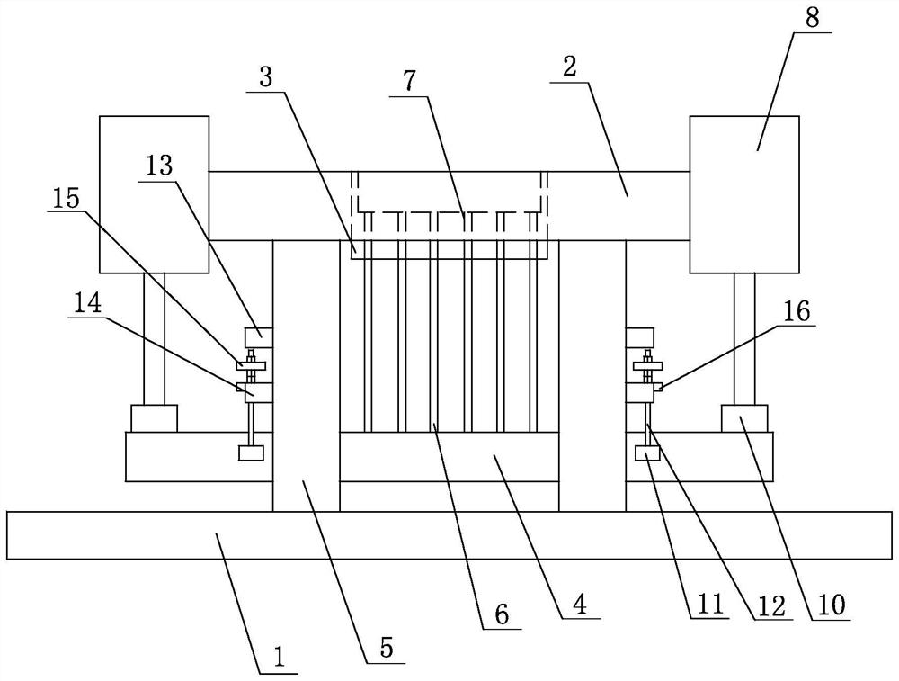
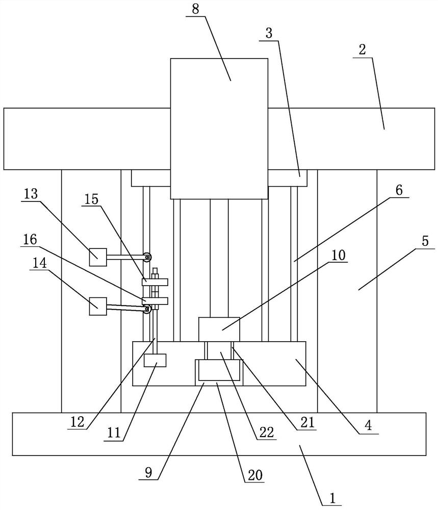
[0021] Embodiment one: see Figure 1~3 As shown, a stripping plate installation structure for an injection mold includes a bottom plate 1, a mounting plate 2, a die 3 and a stripping plate 4, the die is installed inside the mounting plate, and the bottom surface of the mounting plate has four The corners are respectively connected to the top surface of the bottom plate via a vertical plate 5, the stripper plate is installed between the bottom plate and the installation plate, and multiple groups of ejector rods are arranged on the top surface of the support plate 6. There are multiple sets of stripping holes 7 in the die, the top of each set of ejector rods is inserted into a set of stripping holes, and the left and right sides of the mounting plate are respectively provided with a The hydraulic cylinder 8, the left side and the right side of the stripper plate are respectively arranged on the left side and the right side outside the installation plate;

[0022] The left side...


PUM


Abstract

The invention discloses an injection mold stripper plate mounting structure. The injection mold stripper plate mounting structure comprises a bottom plate, a mounting plate, a female mold, a stripperplate and multiple sets of vertical plates, and is characterized in that the left side and the right side of the mounting plate are each correspondingly provided with a hydraulic cylinder, and the left side and the right side of the stripper plate are respectively arranged outside the left side and the right side below the mounting plate; the left side and the right side of the stripper plate areeach provided with a connecting groove, a connecting rod is arranged on an output shaft of each hydraulic cylinder, the output shaft of each hydraulic cylinder is inserted into the corresponding connecting groove through the corresponding connecting rod, and the stripper plate is driven to move up and down through stretching and retracting of the output shafts of the hydraulic cylinders; and two sets of travel switches are arranged on the side wall of one set of the vertical plates on the right side, a positioning mechanism is arranged at the right end of the stripper plate, and the positioning mechanism is arranged between the two sets of travel switches. According to the structure, the stripping stability and quality are improved.

Description

technical field [0001] The invention relates to the field of injection molding, in particular to a mounting structure for a stripping plate of an injection mold. Background technique [0002] When using an injection mold to inject plastic products, under normal circumstances, after the mold is opened, the movement of the stripper plate will be used to push the ejector rod to eject the product in the mold to realize the stripping work. In the prior art, connecting rods are generally used to connect the stripping plate to the injection molding machine. In this way, the connection and installation of the injection mold and the injection molding machine is not convenient enough, and the stroke of the connecting rod driven by the injection molding machine is limited, which affects the stripping. material. Therefore, how to solve the above technical problems is the direction that those skilled in the art need to work on. Contents of the invention [0003] The purpose of the pr...

Claims


Application Information

Patent Timeline
IPC IPC(8): B29C45/40B29C45/76B29C45/82
CPCB29C45/4005B29C45/7626B29C45/82B29C2945/76896
Inventor 杨光辉戴卫卫李春晓
Owner 常熟华新汽车零部件有限公司
Why Eureka
Try Eureka