Simply supported bridge expansion device with two ends capable of rotating in multiple directions and mounting method

A telescopic device, simply supported technology, used in bridges, bridge parts, bridge construction and other directions, can solve the problems of the fixed end of the bolt with additional force cannot be displaced, the rotation system is unreasonable, the unsafe jumping, etc., to avoid rotation The effect of preventing obstacles, avoiding additional force, and ensuring driving safety

Active Publication Date: 2021-01-01
西安华盾工程科技有限公司
View PDF17 Cites 0 Cited by
  • Summary
  • Abstract
  • Description
  • Claims
  • Application Information

AI Technical Summary

Problems solved by technology

[0018] This application provides a simply supported bridge telescopic device with multi-directional rotation at both ends and an installation method to solve the unreasonable rotation system of the existing device, the unsafe jumping under the impact of the vehicle, and the additional force and fixation of the bolts Problems such as the end cannot be changed

Method used


Image

  • Simply supported bridge expansion device with two ends capable of rotating in multiple directions and mounting method
  • Simply supported bridge expansion device with two ends capable of rotating in multiple directions and mounting method
  • Simply supported bridge expansion device with two ends capable of rotating in multiple directions and mounting method

Examples


Embodiment 1

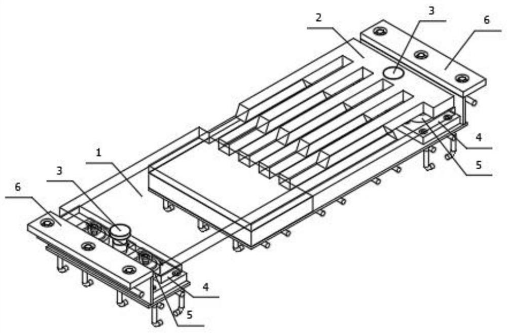
[0088] Please refer to the attached Figure 1~3 , with Figure 1~3 The elevation view, installation front view and left view of a simply supported bridge telescopic device with multi-directional rotation at both ends provided in Embodiment 1 of the present application. As shown in the figure, the bridge telescopic device in Embodiment 1 includes a movable end The expansion plate 1 and the fixed end expansion plate 2, one end of the movable end expansion plate 1 and one end of the fixed end expansion plate 2 are connected with the balance weight 4 through the horizontal limit column 3, and the other ends are arranged alternately at the fixed end. 4 on;

[0089] The balance weight 4 is fixedly connected with the movable displacement mechanism 5;

[0090] The movable displacement mechanism 5 is fixedly connected with the pre-installed component 6;

[0091] An elastic support 7 is provided at the edge between the balance weight 4 at the fixed end and the pre-installed assembly ...

Embodiment 2

[0114] In the drawings used in Embodiment 2, the same reference numerals as in Embodiment 1 still use the definitions in Embodiment 1.

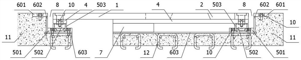
[0115] Exemplary, such as Figure 13 Shown is the installation front view of a simply-supported bridge expansion device provided by Embodiment 2 of the present application that can rotate in multiple directions. For the sake of simplicity, only the differences between Embodiment 2 and Embodiment 1 will be described below.

[0116] Exemplary, such as Figures 14 to 16 Shown are the front view, left view and front view of the pre-installation assembly 6 at the movable end and the pre-assembly assembly 6 at the fixed end. As shown in the figure, the difference from Embodiment 1 is that the upper end of the vertical plate 602 snaps into the cover plate 601 is inserted into the groove on the bottom surface, and the lower end is inserted into the groove on the top surface of the bottom plate 603 .

[0117] Anchor assembly 604 includes several suc...


PUM


Abstract

The invention discloses a simply supported bridge expansion device with two ends capable of rotating in multiple directions. The device comprises an expansion plate rotationally connected with a balance block through a horizontal limiting column, horizontal rotation of the expansion device is realized, a movable displacement mechanism is fixedly connected with the balance block to prevent overturning caused by single-fulcrum rotation, a pre-assembly component is fixedly connected with the movable displacement mechanism, a first movable gap is formed between the expansion plate and the pre-assembly component, an elastic support is arranged on the edge between the balance block on a fixed end and the pre-assembly component, the elastic support and an upper structure form a complete supporting channel, multi-directional displacement of the fixed end is achieved, and meanwhile the bumping phenomenon caused by the fulcrum effect generated when a vehicle passes through and additional stressof a horizontal limiting column are avoided. When falling back, the end part of the expansion plate forms a stable transition surface with an adjacent structure, so that driving safety of the vehicleis ensured. The invention further provides a mounting method of the simply supported bridge expansion device with the two ends capable of rotating in multiple directions, field construction and installation are greatly facilitated through the pre-assembly and modular sequential mounting mode, and later maintenance and repair are facilitated.

Description

technical field [0001] The present application relates to the field of bridge structure construction, in particular to a simply supported bridge telescopic device and an installation method with both ends capable of rotating in multiple directions. Background technique [0002] In order to meet the needs of bridge deck deformation, bridge expansion devices must be installed at the bridge joints, and the bridge expansion devices must meet the following basic functions: [0003] 1 Bearing function, the bridge telescopic device must be installed at the gap between the beam ends to form a continuous bearing surface to ensure the smooth passage of vehicles. [0004] 2. Displacement function. The bridge expansion device must adapt to the expansion and contraction displacement caused by the temperature change, shrinkage, creep and load of the beam body. [0005] 3. Anchoring function. The bridge expansion device is installed in the later stage of the project and must be reliably a...

Claims


Application Information

Patent Timeline
Patent Type & Authority Applications(China)
IPC IPC(8): E01D19/06E01D21/00
CPCE01D19/065E01D21/00
Inventor 孟津杨辉李静
Owner 西安华盾工程科技有限公司
Why Eureka
Try Eureka