A simply-supported bridge telescopic device capable of rotating in multiple directions at both ends and its installation method
A telescopic device and simply supported technology, which is applied in the direction of bridges, bridge construction, bridge parts, etc., can solve problems such as unsafe vehicle jumping, fixed ends of bolts with additional force cannot be displaced, and unreasonable rotation system, so as to avoid rotation The effect of obstacles
- Summary
- Abstract
- Description
- Claims
- Application Information
AI Technical Summary
Problems solved by technology
Method used
Image
Examples
Embodiment 1
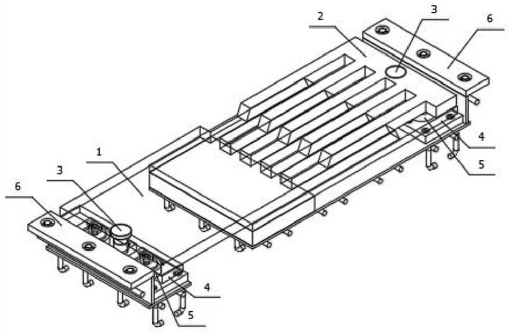
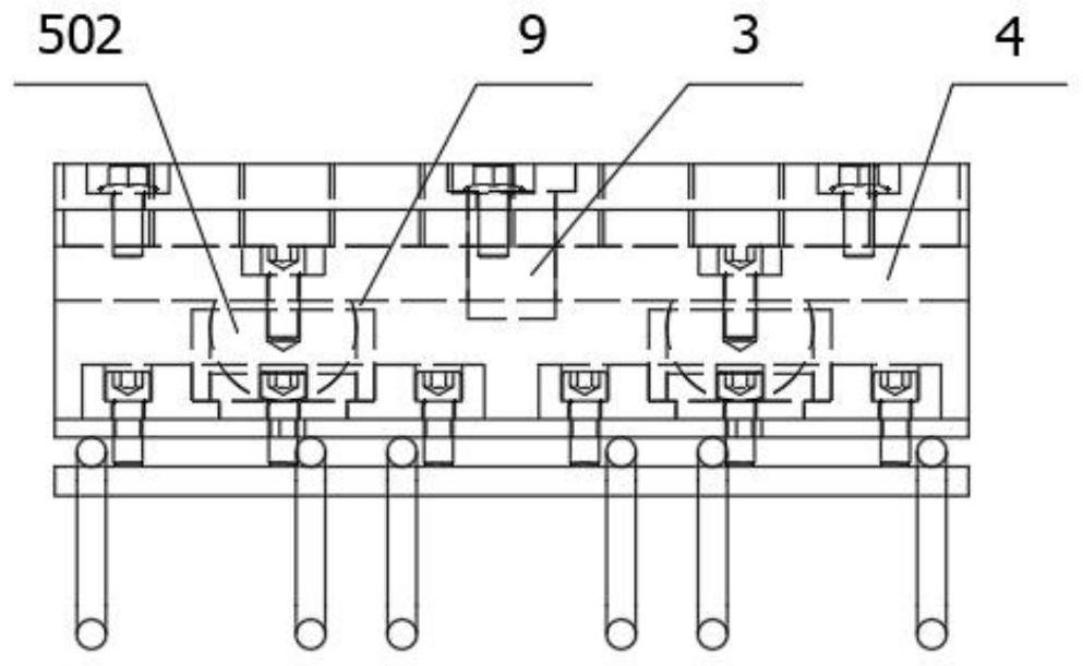
[0088] Please refer to the attached Figure 1~3 , with Figure 1~3 The elevation view, installation front view and left view of a simply supported bridge telescopic device with multi-directional rotation at both ends provided in Embodiment 1 of the present application. As shown in the figure, the bridge telescopic device in Embodiment 1 includes a movable end The expansion plate 1 and the fixed end expansion plate 2, one end of the movable end expansion plate 1 and one end of the fixed end expansion plate 2 are connected with the balance weight 4 through the horizontal limit column 3, and the other ends are arranged alternately at the fixed end. 4 on;
[0089] The balance weight 4 is fixedly connected with the movable displacement mechanism 5;
[0090] The movable displacement mechanism 5 is fixedly connected with the pre-installed component 6;
[0091] An elastic support 7 is provided at the edge between the balance weight 4 at the fixed end and the pre-installed assembly ...
Embodiment 2
[0114] In the drawings used in Embodiment 2, the same reference numerals as in Embodiment 1 still use the definitions in Embodiment 1.
[0115] Exemplary, such as Figure 13 Shown is the installation front view of a simply-supported bridge expansion device provided by Embodiment 2 of the present application that can rotate in multiple directions. For the sake of simplicity, only the differences between Embodiment 2 and Embodiment 1 will be described below.
[0116] Exemplary, such as Figures 14 to 16 Shown are the front view, left view and front view of the pre-installation assembly 6 at the movable end and the pre-assembly assembly 6 at the fixed end. As shown in the figure, the difference from Embodiment 1 is that the upper end of the vertical plate 602 snaps into the cover plate 601 is inserted into the groove on the bottom surface, and the lower end is inserted into the groove on the top surface of the bottom plate 603 .
[0117] Anchor assembly 604 includes several suc...
PUM
 Abstract
Description
Claims
Application Information
 - R&D
- Intellectual Property
- Life Sciences
- Materials
- Tech Scout
- Unparalleled Data Quality
- Higher Quality Content
- 60% Fewer Hallucinations
Browse by: Latest US Patents, China's latest patents, Technical Efficacy Thesaurus, Application Domain, Technology Topic, Popular Technical Reports.
© 2025 PatSnap. All rights reserved.Legal|Privacy policy|Modern Slavery Act Transparency Statement|Sitemap|About US| Contact US: help@patsnap.com


