
Throttle-free sand blasting sliding sleeve

A non-throttle, sliding sleeve technology, used in the production of fluids, wellbore/well components, earth-moving drilling, etc., can solve problems such as the inability to meet the needs of large-scale fracturing construction, reduce erosion damage, and improve safety. , to avoid the effect of traffic restrictions

Inactive Publication Date: 2021-01-01
CNPC BOHAI DRILLING ENG +1
View PDF11 Cites 0 Cited by
  • Summary
  • Abstract
  • Description
  • Claims
  • Application Information

AI Technical Summary

Problems solved by technology

[0004] The purpose of the present invention is to provide a method to solve the problem in the multi-stage layered fracturing string caused by the hole diameter of the ball seat of the conventional sandblasting sliding sleeve decreases from top to bottom with the increase of the number of layered fracturing stages. Unthrottled sandblasting sliding sleeves with cumulative throttling effect formed in the cracked pipe string, and the existing structure cannot meet the needs of large-scale fracturing construction

Method used


Image

  • Throttle-free sand blasting sliding sleeve
  • Throttle-free sand blasting sliding sleeve
  • Throttle-free sand blasting sliding sleeve

Examples


Embodiment 1

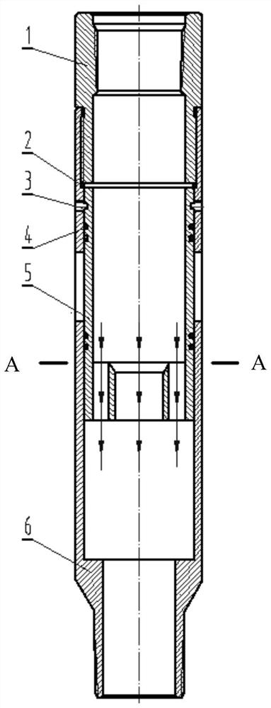
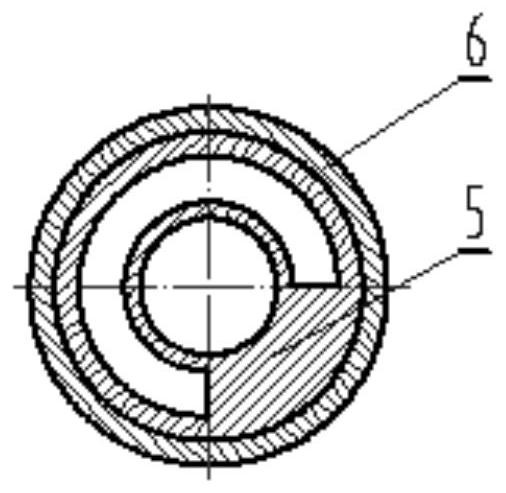
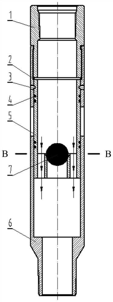
[0031] As shown in FIG. 1( a ) and FIG. 1( b ), the non-throttling sand blaster sliding sleeve includes an upper joint 1 , a non-throttling inner sliding sleeve 5 , a sandblasting sliding sleeve main body 6 and a soluble ball 7 .

[0032] The non-throttle inner sliding sleeve 5 includes an outer cylinder and an inner cylinder. The axial length of the inner cylinder is smaller than that of the outer cylinder, and the inner cylinder is centrally arranged inside the bottom end of the outer cylinder with a gap between the inner cylinder and the outer cylinder. The unrestricted inner sliding sleeve 5 is characterized in that its lower part is a double-layer flow channel structure, including the inner layer ball seat channel formed based on the inner cylinder and based on the gap between the outer cylinder and the inner cylinder. The outer flow complementary channel formed by the annular space of the outer layer, the two channels together form the flow channel.

[0033] The diameter...

Embodiment 2

[0041] Such as Figure 4 Shown is the seven-stage fracturing string formed by using the unrestricted sandblasting sliding sleeve of Example 1 to meet the 7-stage fracturing in the 5-1 / 2" production casing; specifically,

[0042] The seven-stage fracturing string includes a bell mouth A connected sequentially through tubing K from bottom to top, an unrestricted self-service unpacking packer B, a first-stage unrestricted sandblasting sleeve C, an unrestricted self-service Unpacking packer B, second-stage unthrottled sandblasting sleeve D, unthrottled self-unpacking packer B, third-stage unthrottled sandblasting sleeve E, unthrottled self-unpacking B, the fourth-stage unrestricted sandblasting sleeve F, unrestricted self-unpacking packer B, the fifth unrestricted sandblasting sleeve G, unrestricted self-unpacking packer B, the first Six-stage unrestricted sandblasting sliding sleeve H, unrestricted self-service unpacking packer B, sand control hydraulic anchor I and hydraulic saf...


PUM


Abstract

The invention discloses a throttle-free sand blasting sliding sleeve. The throttle-free sand blasting sliding sleeve comprises a throttle-free inner sliding sleeve body, a sand blasting sliding sleevemain body and a soluble ball, the throttle-free inner sliding sleeve body comprises an outer cylinder and an inner cylinder with the axial length smaller than that of the outer cylinder, and the inner cylinder is arranged on the inner side of the bottom end of the outer cylinder in a sleeving mode in a gap mode and connected with the outer cylinder into a whole through a connecting part; the sandblasting sliding sleeve main body is a cylinder body with a plurality of sand blasting holes formed in the upper side wall, and a circle of limiting step with the inner diameter slightly larger thanthe outer diameter of the inner cylinder is arranged on the lower inner wall; the soluble ball is used for plugging the inner cylinder; the throttle-free inner sliding sleeve body is fixed into the sand blasting sliding sleeve main body through a plurality of shear pins and seals the sand blasting holes; the axial length from the top surface of the throttle-free inner sliding sleeve body to the hole walls of the lower sides of the sand blasting holes is less than or equal to the axial length from the bottom surface of the throttle-free inner sliding sleeve body to the upper end surface of thelimiting step. The throttle-free sand blasting sliding sleeve can achieve the functions that the sand blasting holes are not throttled, and multi-stage layered fracturing is used, erosion damage of fracturing fluid to the sand blasting holes and a production casing pipe is reduced, and the safety of a fracturing pipe column and the production casing pipe is improved.

Description

technical field [0001] The invention relates to the technical field of oil and gas field fracturing operations, in particular to an unthrottled sandblasting sliding sleeve. Background technique [0002] In recent years, with the deepening of domestic oil and gas field development, the "K344 packer + sandblasting sliding sleeve" layered fracturing technology has become the main technology to improve the single well production of oil and gas fields. This technology uses the K344 packer to realize the interlayer isolation of the fracturing interval, and establishes the communication channel between the fracturing string and the reservoir through the sandblasting sliding sleeve, which can realize multi-stage layered fracturing and fracturing in one trip. The purpose of layer production. Among them, the sandblasting sliding sleeve is an important tool to realize this technology. [0003] The current structure design of the sandblasting sliding sleeve is in the form of throwing ...

Claims


Application Information

Patent Timeline
Patent Type & Authority Applications(China)
IPC IPC(8): E21B43/26E21B34/14
CPCE21B34/14E21B43/26
Inventor 韩永亮冯强丁柯宇王玥周后俊詹鸿运刘志斌杨晓勇郭鸣窦占强
Owner CNPC BOHAI DRILLING ENG
Learn More