Three-stage throttling valve

A choke valve and throttling piece technology, applied in the direction of lift valve, valve details, valve device, etc., can solve the problems of reducing internal flow rate, unable to ensure long-term normal operation of shale gas production and transportation, etc., to reduce erosion damage , The effect of reducing the gas flow rate and reducing the working intensity

Active Publication Date: 2019-08-23
四川长仪油气集输设备股份有限公司
View PDF7 Cites 2 Cited by
  • Summary
  • Abstract
  • Description
  • Claims
  • Application Information

AI Technical Summary

Problems solved by technology

Therefore, the throttle valve with a single combination of throttle components can no longer guarantee the long-term normal operation of shale gas production and transportation. A throttle valve with multi-stage combined throttle components is needed to reduce the pressure of high-speed gas in stages in the valve, reducing the The internal flow rate reduces the grinding of the valve trim by the fluid entrained with sand and gravel

Method used


Image

  • Three-stage throttling valve
  • Three-stage throttling valve
  • Three-stage throttling valve

Examples


Embodiment 1

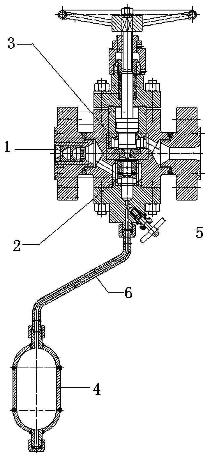
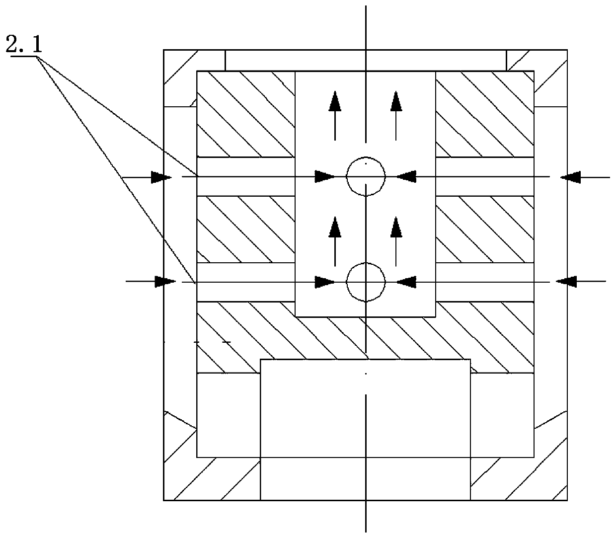
[0026] As a most basic embodiment of the present invention, such as figure 1, a three-stage throttling throttle valve disclosed in this embodiment, includes a valve body with a pressure inlet and a pressure outlet, and in the valve body, between the pressure inlet and the pressure outlet, there is a valve core 3.2 The channel port that controls the opening and closing is connected; the produced gas enters the valve body from the pressure inlet port and passes out from the pressure outlet port through the channel port, and the produced gas enters at a low level and exits at a high level between the pressure inlet port and the pressure outlet port; The outlet of the pressure inlet is provided with a throttling piece I1 for throttling and reducing pressure; the passage port is provided with a throttling piece II2 for removing impurities in the produced gas through hedging; Pressure protection valve core 3.2 throttling piece III3. Throttle piece Ⅰ1, throttle piece Ⅱ2, and throttl...

Embodiment 2

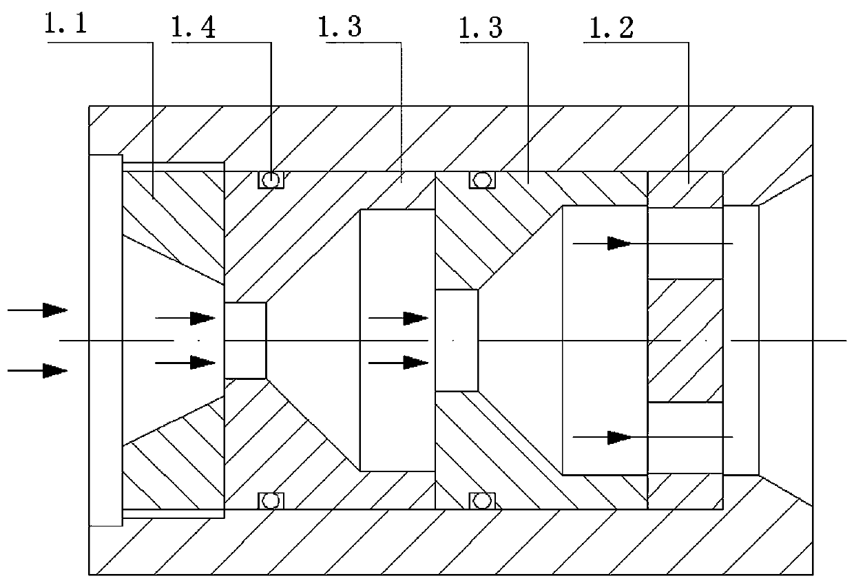
[0029] As a preferred embodiment of the present invention, on the basis of the above-mentioned Example 1, further, as figure 2 As shown, the throttling piece I1 includes several pressure-reducing plates 1.3 arranged between the pressure ring 1.1 at the inlet end and the baffle plate 1.2 at the outlet end in the pressure inlet. The perforated plate with the opening diameter of the outlet port, the baffle plate 1.2 is an orifice plate with several openings smaller than the opening diameter of the outlet port of the orifice plate, the openings of the pressure ring 1.1, the orifice plate and the baffle plate 1.2 form a The throttling and pressure-reducing channel through which the produced gas passes; pressure ring 1.1, pressure-reducing plate 1.3, and baffle plate 1.2 are sequentially transferred from the inner hole of the flange to the pressure-inlet channel, and finally tightened by pressure ring 1.1, and the pressure-reducing plate 1.3 is the inlet The diameter of the port op...


PUM


Abstract

The invention belongs to the technical field of stop valve structures, and discloses a three-stage throttling valve. The three-stage throttling valve comprises a valve body with a pressure inlet and apressure outlet, a passage opening controlled by a valve core to be opened or closed is arranged in the valve body to communicate the pressure inlet and the pressure outlet, produced gas enters the valve body from the pressure inlet and exits from the pressure outlet through the passage opening, the produced gas enters the pressure inlet with low pressure and exits from the pressure outlet with high pressure, the pressure inlet is provided with a throttling part I for throttling and depressurizing, a throttling part II for removing impurities of the produced gas through opposite flow is arranged at the passage opening, and the valve core is provided with a throttling part III which protects the valve core through staged depressurization.

Description

technical field [0001] The invention belongs to the technical field of transport devices for shale produced gas, and in particular relates to a three-stage throttling throttle valve. Background technique [0002] After the shale gas is extracted from the wellhead, due to the high pressure, it is necessary to use a high-pressure throttle valve to reduce the pressure and then transport it to the back-end treatment plant. [0003] The produced shale gas contains more grains of sand and dust. However, in the state of high-pressure differential throttling of traditional throttle valves, the high-speed fluid entrains sand and gravel to grind the throttling elements continuously, causing the throttling elements to quickly If the damage fails, production has to be stopped for inspection and maintenance, causing great trouble to shale gas exploitation. Therefore, the buffer design in the throttle valve has become a very important issue. [0004] In the prior art, such as the previo...

Claims


Application Information

Patent Timeline
Patent Type & Authority Applications(China)
IPC IPC(8): F16K1/36F16K1/42F16K1/32F16K27/02
CPCF16K1/32F16K1/36F16K1/42F16K27/02
Inventor 王元清张月伟张文文黄世强
Owner 四川长仪油气集输设备股份有限公司
Why Eureka
Try Eureka