Bridge plug with sand production prevention function for fracturing and using method thereof
A fracturing and functional technology, applied in the field of bridge plugs for fracturing, can solve problems such as blockage, erosion damage of gas pipelines, etc.
- Summary
- Abstract
- Description
- Claims
- Application Information
AI Technical Summary
Problems solved by technology
Method used
Image
Examples
Embodiment 1
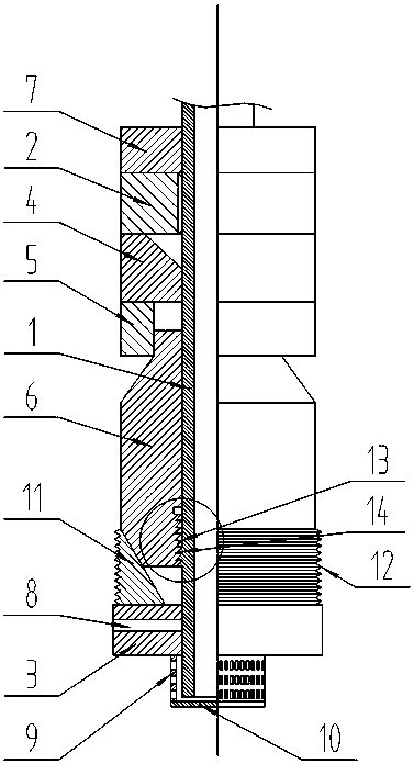
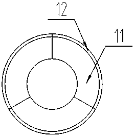
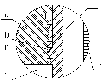
[0030] Referring to Fig. 1, it is a structural schematic diagram of Embodiment 1 of the present invention, a bridge plug for fracturing with the function of preventing sand production, including: a central tube 1, a setting push cylinder 6, a base 3, a ball seat 4, and a sealant Cylinder 5, setting cylinder 2, locking part and explosives 7, the center tube 1 is in order from bottom to top seat cover base 3, locking part, setting push cylinder 6, sealing rubber cylinder 5, ball seat 4, seating The sealing cylinder 2 and the explosive 7, the explosive 7, the setting cylinder 2, the ball seat 4, and the sealing rubber cylinder 5 are in contact with each other, and the lower end of the setting push cylinder 6 is in contact with the locking part and is located in the locking part, so The top end of the setting push cylinder 6 is located in the sealing rubber cylinder 5, and the explosive 7, the setting cylinder 2, the ball seat 4, the sealing rubber cylinder 5 and the inner peripher...
Embodiment 2
[0033] Referring to Fig. 1, compared with Embodiment 1, the difference of this embodiment is that: there are shear studs 8 fixedly connected between the base 3 and the central pipe 1, and there are at least two pairs of shear studs 8, and at least two The pair of shear studs 8 are evenly distributed between the base 3 and the central tube 1 .
[0034] In actual use: while the setting cylinder 2 pushes the slips 11 to move outward, the base 3 is moved down by the impact force, so that the shear nail 8 between the center tube 1 and the base 3 is broken, and the center tube 1 is separated from the base 3 .
Embodiment 3
[0036] Referring to Fig. 1, compared with Embodiment 2, the difference of this embodiment is that: the lower surface of the base 3 is fixed with a sand control net 9, and the bottom end of the central pipe 1 is located in the sand control net 9.
[0037] In actual use: After the fracturing of the upper section of the soluble fracturing plugging ball is completed, the gaseous or liquid fluid in the formation carries solid proppant or formation filling and enters the wellbore. When it flows to the position of the sand control net 9, the solid The material is blocked by the sand control net 9 and cannot flow to the wellhead.
PUM
 Abstract
Description
Claims
Application Information
 - R&D
- Intellectual Property
- Life Sciences
- Materials
- Tech Scout
- Unparalleled Data Quality
- Higher Quality Content
- 60% Fewer Hallucinations
Browse by: Latest US Patents, China's latest patents, Technical Efficacy Thesaurus, Application Domain, Technology Topic, Popular Technical Reports.
© 2025 PatSnap. All rights reserved.Legal|Privacy policy|Modern Slavery Act Transparency Statement|Sitemap|About US| Contact US: help@patsnap.com


