A zero-current sampling method of a bridgeless PFC circuit and its circuit

A zero-current detection and circuit technology, applied in the direction of high-efficiency power electronic conversion, electrical components, output power conversion devices, etc., can solve the problems of high cost, complex hardware circuits, and many electronic components, and achieve low product cost and circuit. Simple solution and fast response

Active Publication Date: 2022-03-18
MORNSUN GUANGZHOU SCI & TECH
View PDF7 Cites 0 Cited by
  • Summary
  • Abstract
  • Description
  • Claims
  • Application Information

AI Technical Summary

Problems solved by technology

[0010] Publication No. US9899909B2 discloses a totem pole bridgeless power factor correction (PFC) soft switch control device and method, such as Figure 2a , Figure 2b , Figure 2c As shown (respectively derived from the patent attached Figure 4 , attached Figure 7 , Accompanying drawing 8), it can be seen intuitively from the accompanying drawings that the patent solution requires at least three logic gate devices and a comparator, the hardware circuit is complex, there are many electronic components, and the cost will be relatively high
[0011] As analyzed above, the zero-current detection circuit in the current bridgeless PFC circuit still has certain defects.

Method used


Image

  • A zero-current sampling method of a bridgeless PFC circuit and its circuit
  • A zero-current sampling method of a bridgeless PFC circuit and its circuit
  • A zero-current sampling method of a bridgeless PFC circuit and its circuit

Examples


no. 1 example

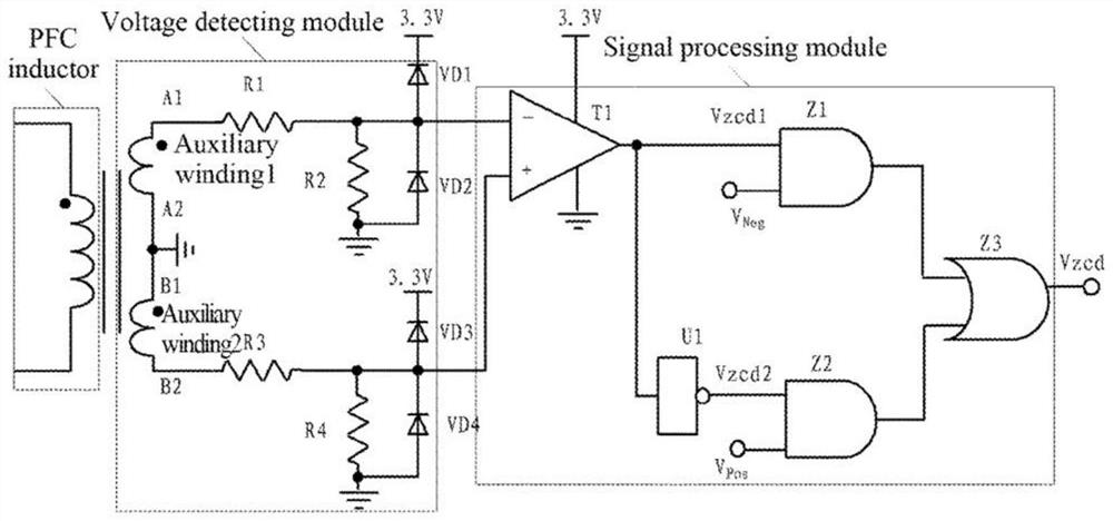
[0040] The application schematic diagram of the zero current detection circuit of the bridgeless PFC circuit in the first embodiment of the present invention is as follows Figure 4 As shown, a detection winding is used to couple to the magnetic core of the inductor L1, and the zero current detection is realized through the induced voltage generated by it. The zero current detection circuit of the bridgeless PFC circuit in the first embodiment includes: a first detection winding Ns1, a first resistor R1, a second resistor R2, a third resistor R3, a fourth resistor R4, a third switch tube Q3 and a fourth switch Tube Q4. The connection relationship is: the first end of the first detection winding Ns1 is respectively connected to the first end of the first resistor R1 and the first end of the third resistor R3, and the second end of the third resistor R3 is connected to the second end of the fourth resistor R4. end connected to obtain the ZCD trigger signal detection point, the ...


PUM


Abstract

The invention discloses a zero-current detection method of a bridgeless PFC circuit and its circuit. The invention uses a detection winding coupled to the inductance of a bridgeless PFC circuit to generate an induced voltage, and then sets the winding and resistance to generate two midpoints. Take one midpoint as the ZCD trigger signal detection point, and take the other midpoint as the reference ground of the ZCD trigger signal detection point. The voltage between the ZCD trigger signal detection point and the reference ground is the ZCD trigger signal required for zero current detection: inductance When demagnetizing, control the ZCD trigger signal detection point and another midpoint through the switching device without current passing through, so that the switched-on switching device and its corresponding resistance are in a floating state; when inductive excitation, control the ZCD trigger signal detection through the switching device The voltage value of the point and the other midpoint are equal. The method or circuit of the invention can realize the zero current detection of the inductance of the bridgeless PFC circuit, and then complete the control of the bridgeless PFC circuit, and the circuit structure of the invention is simple, the cost is low, and the signal processing is simple.

Description

technical field [0001] The invention relates to the field of bridgeless PFC circuits, and more specifically, to a zero-current detection method and a circuit thereof. Background technique [0002] Active power factor correction (APFC, ActivePowerFactorCorrection) is widely used in communication power supplies, and the AC input current needs to be sampled in the control of APFC. At present, the bridgeless PFC circuit structure reduces the rectifier bridge, so that the system loss is significantly reduced and the efficiency is significantly improved, so it has received widespread attention. However, in a bridgeless PFC circuit, especially in a totem pole bridgeless PFC circuit, it is difficult to directly detect the zero current of the inductor. Currently, there is no relatively simple, convenient and effective solution for sampling the zero current of the bridgeless PFC circuit. [0003] To solve this difficulty, many researchers have invented patents such as the following: ...

Claims


Application Information

Patent Timeline
Patent Type & Authority Patents(China)
IPC IPC(8): H02M1/42
CPCH02M1/4208H02M1/0009Y02B70/10
Inventor 龙宪良
Owner MORNSUN GUANGZHOU SCI & TECH
Why Eureka
Try Eureka