Sounding optimization method and device of electronic equipment and electronic equipment

A technology for electronic equipment and sound-emitting devices, applied in the field of electronic equipment, can solve the problems that electronic equipment cannot guarantee users' normal calling needs, users cannot listen to the sound of the earpiece, etc.

Active Publication Date: 2021-01-05
VIVO MOBILE COMM CO LTD
View PDF15 Cites 0 Cited by
  • Summary
  • Abstract
  • Description
  • Claims
  • Application Information

AI Technical Summary

Problems solved by technology

[0005] The purpose of the embodiment of the present application is to provide a method and device for optimizing sound generation of electronic equipment and electronic equipment, which can solve the prob

Method used


Image

  • Sounding optimization method and device of electronic equipment and electronic equipment
  • Sounding optimization method and device of electronic equipment and electronic equipment
  • Sounding optimization method and device of electronic equipment and electronic equipment

Examples


example 1

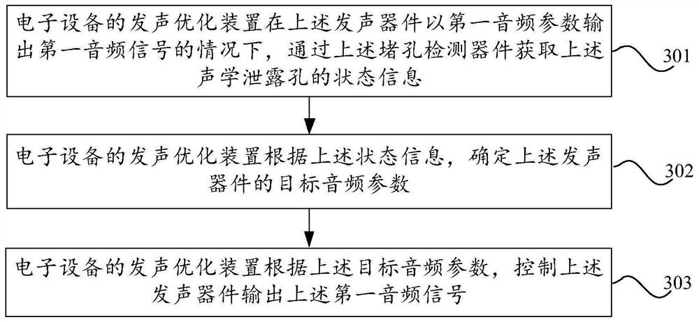
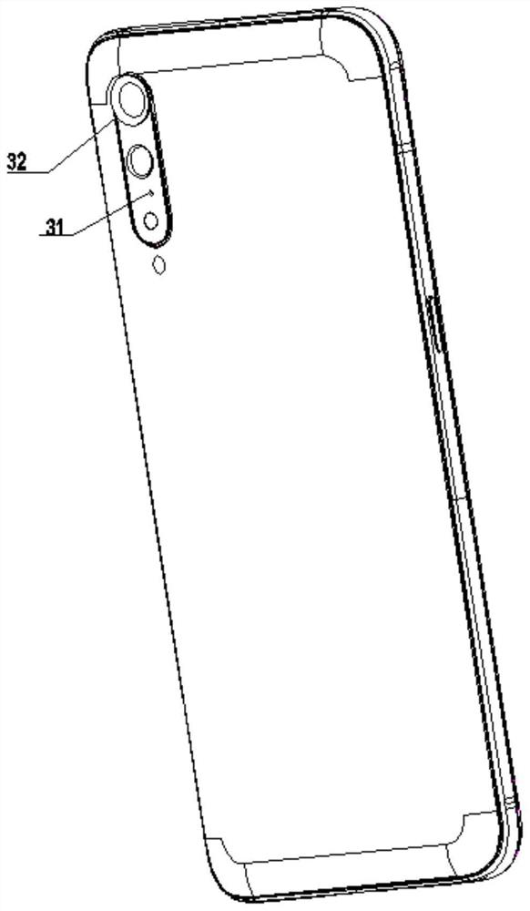
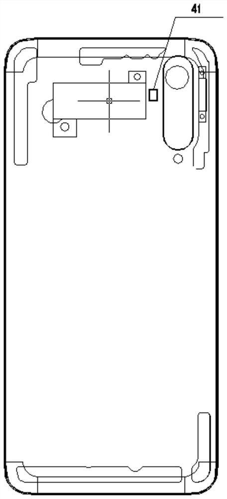
[0083] Example 1: In the case where the hole blocking detection device is the acceleration sensor set on the battery cover of the electronic device, after the acoustic leakage hole is blocked, the air flow cannot flow out smoothly because the rear sound cavity is closed, resulting in a change in the internal sound pressure. Then, the spectral components of the second audio signal change significantly, and the resonant frequency moves to the high frequency direction, that is, the air in the sound guide groove of the rear cavity is in a closed state, the battery cover cannot vibrate, and the amplitude information corresponding to the battery cover will be will be significantly reduced, and the amplitude information of the battery cover corresponding to the second audio signal will be reduced by about 20% compared to the target amplitude information at the same frequency, and then the state information of the acoustic leakage hole can be determined through the significantly reduced...

example 2

[0109] Example 2: Assuming that the acoustic leak hole is not blocked, after the second audio signal from the acoustic leak hole is received by the microphone on the back of the electronic device and around the acoustic leak hole, if the electronic device detects the second audio frequency If the sound pressure levels corresponding to different frequencies of the signal are all smaller than the predetermined threshold, the electronic device can determine that, at this time, the first parameter can be used as the adjustment parameter (that is, the above-mentioned target audio parameter) to adjust the first audio frequency output by the receiver (that is, the above-mentioned sounding device). Signal.

example 3

[0110] Example 3: Assuming that the acoustic leak hole is blocked, after the second audio signal from the acoustic leak hole is received by the microphone on the back of the electronic device and around the acoustic leak hole, if the electronic device detects the second audio signal The sound pressure levels corresponding to different frequencies are greater than the predetermined threshold, then the electronic device can determine that the second parameter can be used as the adjustment parameter (that is, the above-mentioned target audio parameter) to adjust the first audio signal output by the receiver (that is, the above-mentioned sounding device). .

[0111] In this way, when the acoustic leakage hole is blocked, the electronic device can determine the target audio parameter to be adopted by determining the relationship between the second audio signal transmitted from the acoustic leakage hole and the predetermined threshold, so that the acoustic leakage hole is blocked whe...


PUM


Abstract

The invention discloses a sound production optimization method and device of electronic equipment and the electronic equipment, belongs to the technical field of communication, and can solve the problem that the electronic equipment cannot guarantee the normal call demand of a user when an acoustic leakage hole is blocked. The method comprises the following steps: the electronic equipment acquiresstate information of an acoustic leakage hole through a hole blocking detection device under the condition that a sounding device outputs a first audio signal according to a first audio parameter; the electronic equipment determines a target audio parameter of the sound production device according to the state information; and the electronic equipment controls the sounding device to output the first audio signal according to the target audio parameter.

Description

technical field [0001] The present application belongs to the field of communication technologies, and in particular relates to a method, device and electronic device for optimizing sound production of electronic equipment. Background technique [0002] At present, when a user uses an electronic device to make a call, the electronic device will transmit sound in different directions with the receiver as the center. Therefore, other users around the user can easily hear the content of the user's call, resulting in privacy leakage. That is, during the user's call, the privacy leakage problem caused by the sound leakage is easy to occur. [0003] In order to solve the above problems, in the related art, in order to improve the sound leakage problem of the earpiece, a leakage hole opened on the back of the electronic device (for example, a micro-slit beside the camera is opened, and the micro-slit is used as a leakage hole), and at the same time, in the electronic device Set de...

Claims


Application Information

Patent Timeline
IPC IPC(8): H04R29/00
CPCH04R29/001H04R2430/01
Inventor 李乐乐龙立锋
Owner VIVO MOBILE COMM CO LTD
Why Eureka
Try Eureka