Electric vehicle intelligent charging method supporting phase rotation and equipment thereof

An intelligent charging method and technology for electric vehicles, applied in electric vehicle charging technology, electric vehicles, charging stations, etc., can solve the problems of unbalanced three-phase load, affecting the service life of power grid health equipment, etc.

Inactive Publication Date: 2021-01-08
厦门银河龙芯科技有限公司
View PDF7 Cites 3 Cited by
  • Summary
  • Abstract
  • Description
  • Claims
  • Application Information

AI Technical Summary

Problems solved by technology

[0003] The current household charging mode of electric vehicles, especially plug-in electric vehicles, is mainly based on single-phase AC charging, and all use the L1 phase for charging. When multiple vehicles in a station (or community) perform AC charging at the sam

Method used


Image

  • Electric vehicle intelligent charging method supporting phase rotation and equipment thereof
  • Electric vehicle intelligent charging method supporting phase rotation and equipment thereof

Examples


Embodiment 1

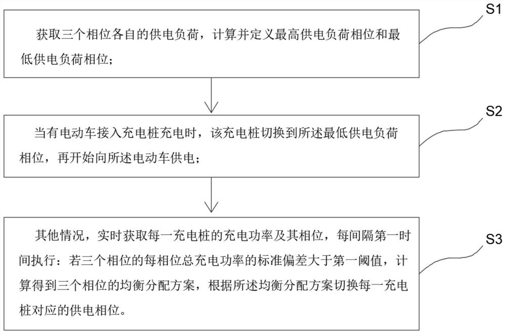
[0035] refer to figure 1 , an electric vehicle intelligent charging method supporting phase rotation, realized by several charging piles, background servers, and phase rotation relay groups, including the following steps:

[0036] S1, obtain the respective power supply loads of the three phases, calculate and define the highest power supply load phase and the lowest power supply load phase;

[0037] Specifically, the background server obtains the power supply loads of the three phases of each charging pile, and obtains the total loads of the three phases after accumulation. Through comparison, the phase with the highest load is defined as the phase with the highest power supply load, and the phase with the highest load Defined as the phase with the highest supply load.

[0038] S2, when an electric vehicle is connected to the charging pile for charging, the charging pile switches to the phase with the lowest power supply load, and then starts to supply power to the electric v...

Embodiment 2

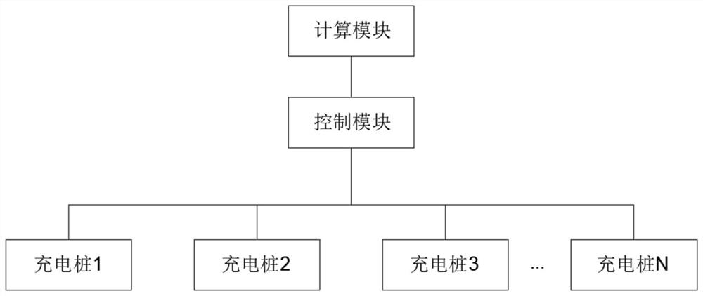
[0053] Further provide an electric vehicle intelligent charging device supporting phase rotation, including:

[0054] refer to figure 2 , a number of charging piles for charging electric vehicles, each of which includes three phase input terminals;

[0055] The calculation module is used for: calculating and defining the highest power supply load phase and the lowest power supply load phase;

[0056] control module for:

[0057] When an electric vehicle is connected to the charging pile for charging, the charging pile switches to the phase of the lowest power supply load, and then starts to supply power to the electric vehicle;

[0058] In other cases, obtain the charging power and its phase of each charging pile in real time, and execute it at the first time every interval: if the standard deviation of the total charging power of each phase of the three phases is greater than the first threshold, calculate the balanced allocation scheme of the three phases , switch the po...


PUM


Abstract

The invention relates to an electric vehicle intelligent charging method supporting phase rotation and equipment thereof, and the method comprises the following steps: obtaining the respective power supply loads of three phases, and calculating and defining the highest power supply load phase and the lowest power supply load phase; when an electric vehicle is connected to a charging pile for charging, switching, by the charging pile, to the lowest power supply load phase, and supplying power to the electric vehicle; under other conditions, obtaining the charging power of each charging pile inreal time, if the standard deviation of the total charging power of each phase of the three phases is larger than a first threshold value, obtaining an equilibrium distribution scheme of the three phases through calculation, and switching the power supply phase corresponding to each charging pile according to the equilibrium distribution scheme. According to the invention, the power supply phase corresponding to each charging pile is switched according to the equilibrium distribution scheme, the impact and damage to a power grid caused by the imbalance of high-power three-phase loads are reduced, and the electric quantity used by the three phases is balanced.

Description

technical field [0001] The invention relates to the field of electric vehicle charging control, in particular to an electric vehicle intelligent charging method supporting phase rotation. Background technique [0002] An electric vehicle refers to a vehicle powered by a vehicle-mounted power supply, driven by a motor to drive the wheels, and conforming to the requirements of road traffic and safety regulations. Due to its smaller impact on the environment than traditional cars, its prospects are widely optimistic. More and more car owners choose to buy electric vehicles when purchasing private cars. The charging pile is a device for charging electric vehicles. [0003] The current household charging mode of electric vehicles, especially plug-in electric vehicles, is mainly based on single-phase AC charging, and all use the L1 phase for charging. When multiple vehicles in a station (or community) perform AC charging at the same time, then The three-phase load of the statio...

Claims


Application Information

Patent Timeline
IPC IPC(8): B60L53/31B60L53/60
CPCB60L53/31B60L53/60Y02T10/70Y02T10/7072Y02T90/12
Inventor 陈兵郭清华郝志强钱金龙龚洋洋
Owner 厦门银河龙芯科技有限公司
Why Eureka
Try Eureka