
Chemical detection sampling device capable of realizing batch sampling and use method

A sampling device, a technology that can be batched, applied in the direction of sampling devices, measuring devices, sampling, etc., can solve troublesome, unfavorable sample sampling efficiency, time-consuming and other problems

Pending Publication Date: 2021-01-08
江苏锦测环保科技有限公司
View PDF0 Cites 0 Cited by
  • Summary
  • Abstract
  • Description
  • Claims
  • Application Information

AI Technical Summary

Problems solved by technology

In this way, closing or opening the sampler back and forth is not only troublesome, but also time-consuming, which is not conducive to improving the sampling efficiency of the sample

Method used


Image

  • Chemical detection sampling device capable of realizing batch sampling and use method
  • Chemical detection sampling device capable of realizing batch sampling and use method
  • Chemical detection sampling device capable of realizing batch sampling and use method

Examples


Embodiment 1

[0038] The specific operation method steps are as follows

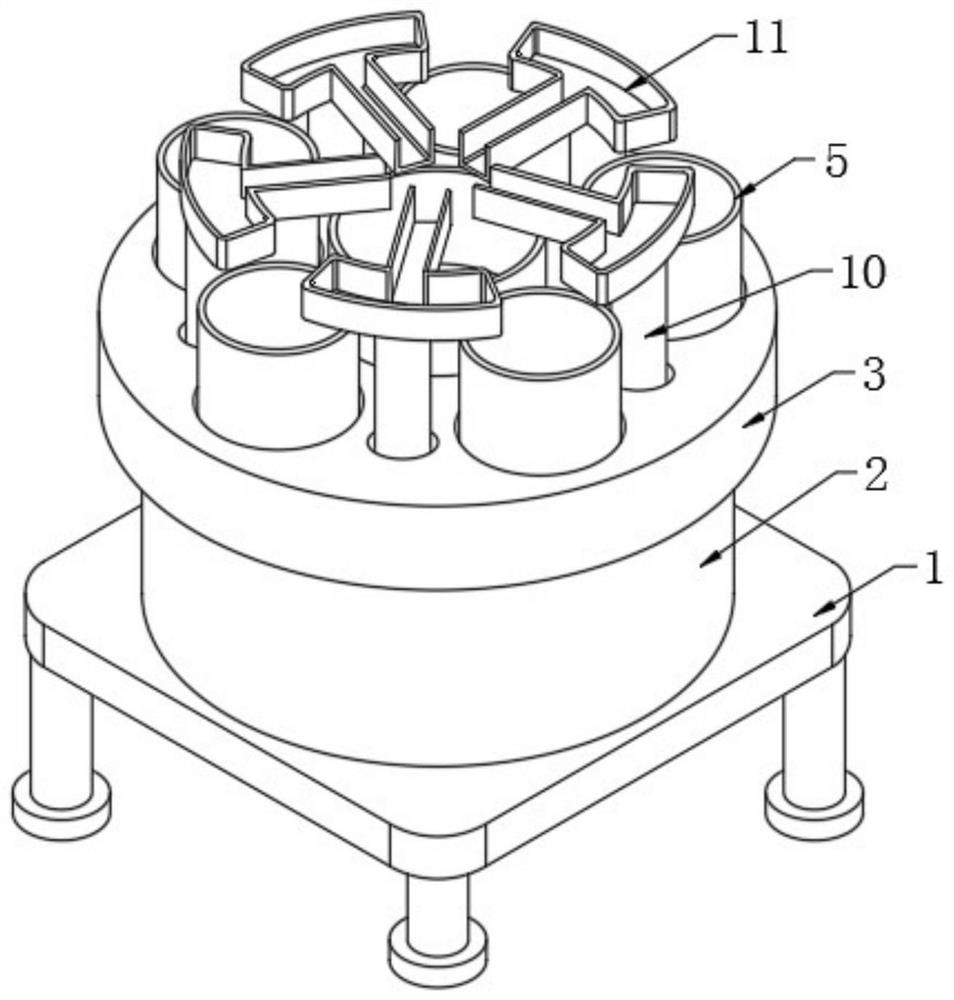
[0039] One of the sampling tanks 5 is placed directly below the sampling tube on the chemical reaction vessel, so that the chemical reagents can flow into the sampling tank 5 automatically.

Embodiment 2

[0041] The specific operation method steps are as follows

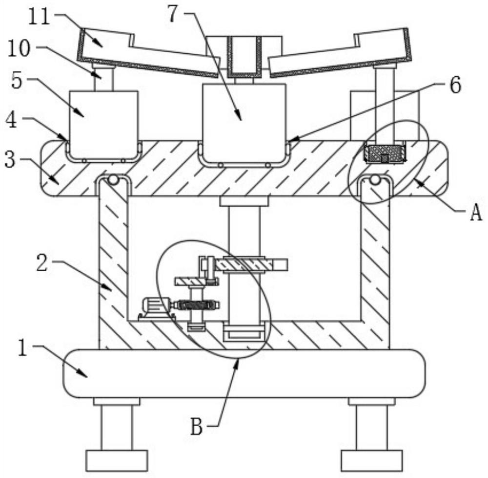
[0042] At the same time start the motor 21, the motor 21 rotates and drives the worm 22 to rotate, the worm 22 drives the worm wheel 20 to rotate, the worm wheel 20 drives the round rod 17 to rotate, the round rod 17 drives the rotating disc 18 to rotate, and the rotating disc 18 drives two Driving rod 19 rotates, and when two driving rods 19 rotate, ring block 14 will be driven to rotate, and when two driving rods 19 all slide out from corresponding guide groove 15, ring block 14 will no longer rotate, and when two When the driving rod 19 entered the corresponding guide groove 15 respectively, the ring block 14 would rotate again, so that the rotating disc 18 could drive the ring block 14 to rotate intermittently through the two driving rods 19, and the ring block 14 could thus drive the The rotating column 13 rotates intermittently, and the rotating column 13 drives the circular plate 3 to rotate intermittently.

Embodiment 3

[0044] The specific operation method steps are as follows

[0045] When the sampling tank 5 was full of chemical reagents soon, the circular plate 3 would rotate once, so that the circular plate 3 would drive the sampling tank 5 full of chemical reagents to spin away from the bottom of the sampling tube, and the empty sampling tank 5 would rotate to the same time. Directly below the sampling tube, when the two sampling tanks 5 rotate past the top of the sampling tube, the chemical reagents flowing out of the sampling tube will flow into the corresponding liquid guiding groove 11, and the chemical reagents that finally enter the liquid guiding groove 11 will flow Into the waste tank 7.


PUM


Abstract

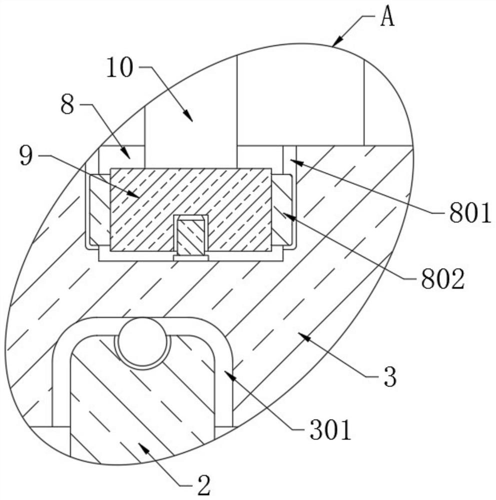
The invention belongs to the technical field of chemical industry production, and relates to a chemical industry detection sampling device capable of achieving batch sampling and a use method thereof.The chemical industry detection sampling device comprises a base; a round box with an opening in the top is formed in the top of the base; a round plate is rotationally installed at the top of the round box; five first clamping grooves arranged in a circle are formed in the top of the round plate; a sampling tank is arranged in each of the five first clamping grooves; a second clamping groove isformed in the circle center of the round plate; a waste tank is arranged in the second clamping groove; five third clamping grooves which are arranged in a circle are formed in the top of the round plate; cylinders are arranged in the five third clamping grooves; connecting rods are fixedly mounted at the top ends of the five cylinders; and liquid guide grooves are fixedly formed in the top ends of the five connecting rods. The sampling device is high in practicability; a worker does not need to close or open the sampler repeatedly when replacing the sampling tank, time is saved, and the sampling and collecting efficiency of samples is improved.

Description

technical field [0001] The invention relates to the technical field of chemical production, in particular to a sampling device for chemical testing capable of sampling in batches and a use method thereof. Background technique [0002] Sampling refers to the process of extracting individuals or samples from the population, that is, the process of conducting experiments or observations on the population. There are two types of random sampling and non-random sampling. The former refers to the sampling method that draws samples from the population according to the principle of randomization, without any subjectivity, including simple random sampling, systematic sampling, cluster sampling and stratified sampling. The latter is a method of drawing samples based on the researcher's point of view, experience or relevant knowledge, which is obviously subjective. In the chemical synthesis process, the control of the reaction process and the reaction end point is a crucial factor. Thi...

Claims


Application Information

Patent Timeline
Patent Type & Authority Applications(China)
IPC IPC(8): G01N1/18G01N1/20
CPCG01N1/18G01N1/20G01N2001/185G01N2001/2021
Inventor 王天宇
Owner 江苏锦测环保科技有限公司
Learn More