
Flux field plate

A flow field plate and flow field technology, applied in separation methods, electrochemical generators, and dispersed particle separation, can solve problems such as heat loss, lower fuel cell system efficiency, and operational stability, and achieve improved flow guidance and improved The effect of the suction effect

Pending Publication Date: 2021-01-08
AUDI AG +1
View PDF2 Cites 0 Cited by
  • Summary
  • Abstract
  • Description
  • Claims
  • Application Information

AI Technical Summary

Problems solved by technology

The disadvantage here is that since these external parts and their connections form additional surfaces at which heat losses can occur
In addition, the efficiency and operating stability of the fuel cell system are reduced due to pressure losses caused by external components and additional installation space must be made available within the fuel cell system

Method used


Image

  • Flux field plate
  • Flux field plate
  • Flux field plate

Examples


Embodiment Construction

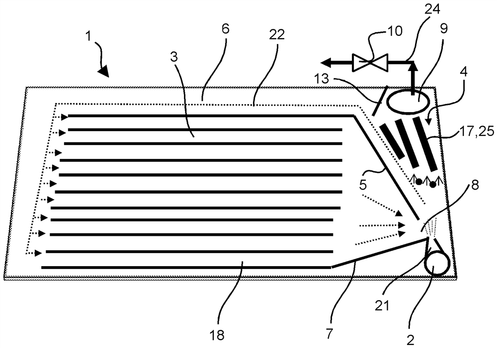
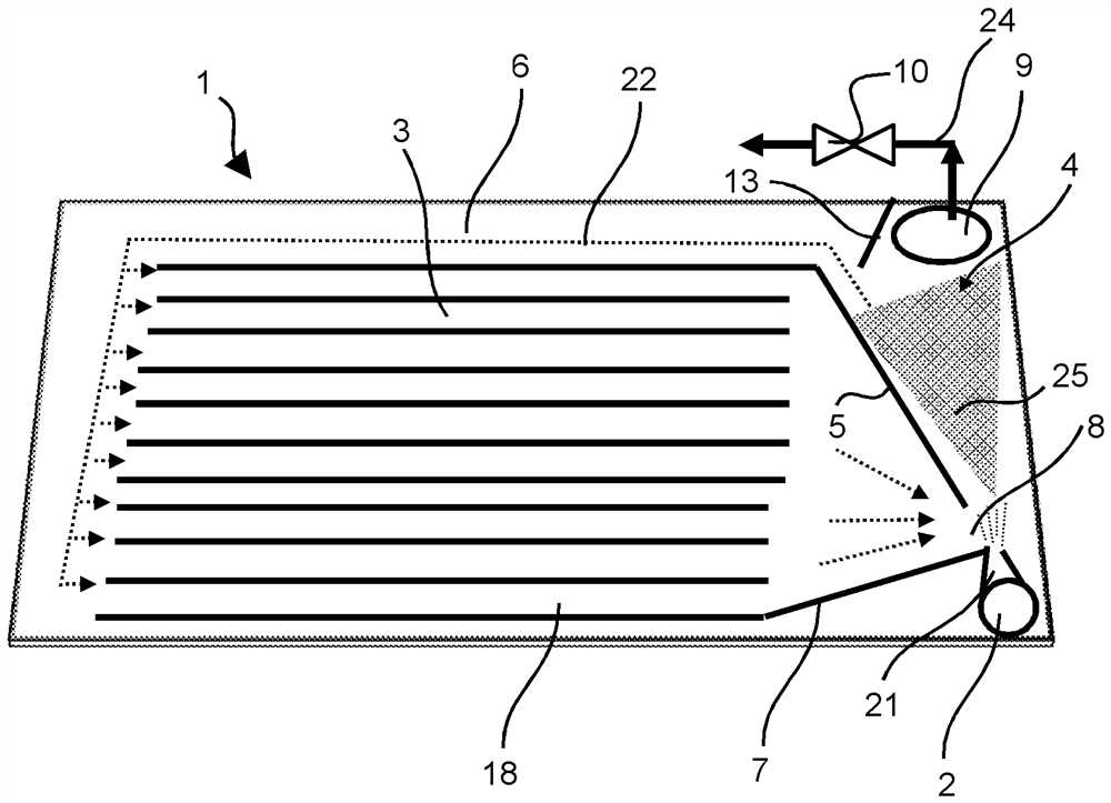
[0023] figure 1 Shown is a flow field plate 1 with gas inlets 2 for distributing reactants to electrodes or gas diffusion layers of a fuel cell. A plurality of channels 3 defining a flow field are arranged on the flow field plate 1 , wherein there is a pressure drop between the gas inlet 2 and the flow field in the flow-through state. This pressure drop causes exhaust gas flowing in channel 3 to be sucked in in the direction of gas inlet 2 . A water-gas separator 4 is additionally arranged on the flow field plate 1 for separating liquid water and / or water vapor from gas, especially waste gas, wherein the water-gas separator 4 is flow-mechanically connected to the flow field in order to The gas separated in the moisture separator 4 is supplied to the flow field again. In other words, the flow field plate 1 enables efficient anode recirculation integrated into the fuel cell or within the fuel cell. Due to the pressure drop, exhaust gas is drawn from the channel 3 of the flow ...


PUM


Abstract

The invention relates to a flux field plate (1) for distribution of a reactant to an electrode or a gas diffusion layer of a fuel cell, having a gas inlet (2), having a plurality of channels (3) defining a flow field. In a state in which flow occurs, a pressure drop is present between the gas inlet (2) and the flow field, which pressure drop leads to an intake of exhaust gas flowing in the channels (3) in the direction of the gas inlet (2). Furthermore, a water-gas separator (4), which is fluid-mechanically connected to the gas inlet (2), is present for separating liquid water and / or water vapor from a gas, which water-gas separator is connected to the flow field in order to supply the gas separated in the water-gas separator (4) to the flow field. A flow cross-section on the gas inlet (2)or on the gas inlet region is smaller than the flow cross-section on or in the region of the water-gas separator (4).

Description

technical field [0001] The invention relates to a flow field plate for distributing reactants to electrodes or gas diffusion layers of a fuel cell, with gas inlets (Gaseinlass), with a plurality of channels defining a flow field, wherein, in There is a pressure drop (Druckgefälle) between the gas inlet and the flow field in the flow-through state, which causes the exhaust gas flowing in the channel to be sucked in in the direction of the gas inlet, as well as the exhaust gas flow mechanically connected to the gas inlet. A water-gas separator for separating liquid water and / or water vapor from gas, which is connected to a flow field so as to supply the gas separated in the water-gas separator to the flow field. Background technique [0002] A fuel cell system generally comprises a fuel cell stack composed of a plurality of fuel cells, which are supplied with fuel on the anode side and cathode gas (usually air) on the cathode side. In order to reduce fuel consumption, the fue...

Claims


Application Information

Patent Timeline
Patent Type & Authority Applications(China)
IPC IPC(8): H01M8/0258H01M8/2483
CPCH01M8/0258H01M8/2483Y02E60/50H01M8/04164B01D45/08B01D46/0031B01D53/261H01M8/04388H01M8/04395
Inventor R·施特克
Owner AUDI AG
Learn More