Fatigue test crack monitoring method and device

A fatigue test and crack technology, applied in measuring devices, using repetitive force/pulsation force to test material strength, image enhancement, etc., can solve problems such as difficulty in comprehensively evaluating the actual damage of cracks to components and difficult to meet engineering needs , to achieve the effect of retaining data accuracy and improving accuracy

Active Publication Date: 2021-01-12
WUHAN UNIV
View PDF5 Cites 7 Cited by
  • Summary
  • Abstract
  • Description
  • Claims
  • Application Information

AI Technical Summary

Problems solved by technology

[0005] The technical problem solved by the present invention is to provide a fatigue test crack monitoring method and device, which solves the problem that the current fatigue test crack monitoring is difficult to comprehensively evaluate the actual harmfulness of cracks to components, and it is difficult to meet the needs of actual engineering in different application scenarios

Method used


Image

  • Fatigue test crack monitoring method and device
  • Fatigue test crack monitoring method and device
  • Fatigue test crack monitoring method and device

Examples


Embodiment Construction

[0034] The present invention will be further described below in conjunction with the accompanying drawings:

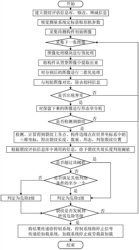
[0035] The fatigue test crack monitoring method according to the embodiment of the present invention includes the following steps:

[0036] S1. Establish a crack assessment information base, including material mechanical properties, dangerous crack patterns of specific materials, and common workpiece dangerous locations. Further, the crack assessment information base is of an interactive type, and the information in the crack assessment information base can be modified, called, increased or decreased as required.

[0037] S2. For example, using a camera array, collect an initial image of the component to be tested and a monitoring image of the component to be tested in the process of bearing the fatigue load. And the camera calibration method is used to obtain the internal and external parameters of the camera for subsequent three-dimensional coordinates. After the i...


PUM


Abstract

The invention discloses a fatigue test crack monitoring method and device, and the method comprises the steps: building a crack evaluation information base, calculating the length, number, position and form of a crack, and comprehensively evaluating the danger level of the crack according to the information in the crack evaluation information base. According to the fatigue test crack monitoring method and device, crack monitoring is achieved through the visual processing technology, the fatigue damage critical point can be accurately judged, and test piece failure information and data accuracyare more completely reserved; in addition, a crack evaluation information base is established, after the length, the number, the positions and the forms of the cracks are calculated, the danger levels of the cracks are comprehensively evaluated according to information in the crack evaluation information base, the actual harmfulness of the cracks to the components is comprehensively evaluated, and the requirements of actual engineering under various component testing conditions and application scenes are met.

Description

technical field [0001] The invention relates to the field of crack detection, in particular to a fatigue test crack monitoring method and device. Background technique [0002] Fatigue is one of the main reasons for the failure of engineering components. In fatigue failure, engineering components are subjected to alternating loads, and after a certain number of cycles, permanent damage is formed locally on the components, and eventually cracks are formed and propagated until fracture, often when the load is lower than its mechanical bearing capacity. Sudden damage occurs, which is far more difficult to prevent than other conventional damages. Fracture caused by fatigue damage is the most common and most dangerous form of fracture in engineering. In the industrial fields involving large-scale components such as the vehicle industry, construction industry, and aviation industry, the safety hazards buried by fatigue and its resulting The loss is even greater. Therefore, it is...

Claims


Application Information

Patent Timeline
Patent Type & Authority Applications(China)
IPC IPC(8): G06T7/00G06T7/12G06T7/13G06T7/136G06T7/155G06T7/62G06T7/80G01N3/32
CPCG06T7/0004G06T7/12G06T7/13G06T7/136G06T7/155G06T7/62G06T7/80G01N3/32G06T2207/10004G06T2207/30164G01N2203/0073
Inventor 陈志文卢文丽刘俐
Owner WUHAN UNIV
Why Eureka
Try Eureka