Main mandrel system, ring rolling machine and ring rolling machine radial main mandrel angle adjustment method

A technology of ring rolling mill and core roll, applied in the direction of rolling, metal rolling, metal rolling, etc., can solve the problems of multi-processing volume, time-consuming and laborious, special-shaped ring forgings that do not meet the design standards, etc.

Active Publication Date: 2021-03-19
CHINA NAT HEAVY MACHINERY RES INSTCO
View PDF6 Cites 0 Cited by
  • Summary
  • Abstract
  • Description
  • Claims
  • Application Information

AI Technical Summary

Problems solved by technology

[0005] The present invention provides a main mandrel roll system, a ring rolling machine and a method for adjusting the radial main mandrel roll angle of the ring rolling machine. Not the same, when rolling with a conventional ring rolling machine, it often occurs that the special-shaped ring forgings do not meet the design standards, and the ring forgings need more follow-up processing in the later stage, which is time-consuming and labor-intensive.

Method used


Image

  • Main mandrel system, ring rolling machine and ring rolling machine radial main mandrel angle adjustment method
  • Main mandrel system, ring rolling machine and ring rolling machine radial main mandrel angle adjustment method

Examples


Embodiment 1

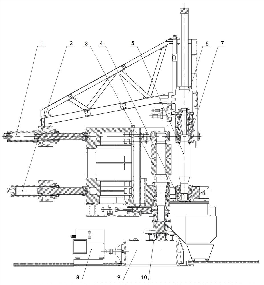
[0034] Please refer to figure 1 , which shows a schematic diagram of the overall structure of a main mandrel system provided by an embodiment of the present invention, the main mandrel system includes:

[0035] Main rolling core roll 5, one end of the main rolling core roll 5 is connected with the first main rolling core roll slider 7 through the first bearing part, and the other end of the main rolling core roll 5 is connected with the second main rolling core roll through the second bearing part The core roller slider 4 is connected;

[0036] Bearing seat guiding device, the bearing seat guiding device is respectively connected with the first main rolling core roller slider 7 and the second main rolling core roller sliding block 4, and the bearing seat guiding device is used for guiding the main rolling core roller The inclination of the mandrel roll 5 is guided, and bears the radial force and the axial force at both ends of the main mandrel roll 5;

[0037] The main rolli...

Embodiment 2

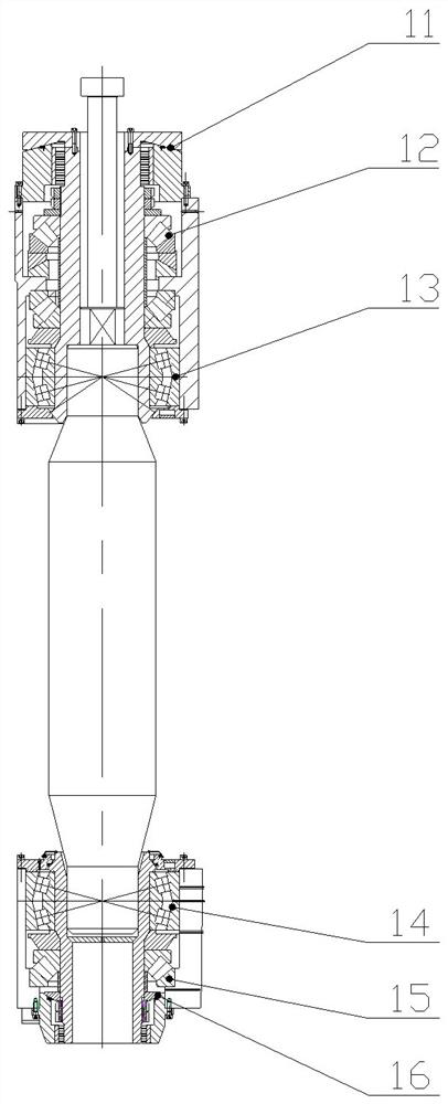
[0044] In one example, another embodiment of the main mandrel system of the present invention is as figure 2As shown, the bearing block guide device includes a first spherical guide rail 11 and a second spherical guide rail 16 oppositely arranged, and the main core roll is located between the first spherical guide rail and the second spherical guide rail, and the The first main core roll slider 7 is in sliding fit with the first spherical guide rail 11 , and the second main core roll slider 4 is in sliding fit with the second spherical guide rail 16 .

[0045] In the above embodiment, the working surface of the first spherical guide rail 11 is slidably matched with one side of the first main core roll slider 7, and the working surface of the second spherical guide rail 16 is matched with one side of the second main core roll slider 4. Slip fit.

[0046] The opening of the first spherical guide rail 11 is opposite to the opening of the second spherical guide rail 16 .

[004...

Embodiment 3

[0049] In an example, please refer to figure 1 , another embodiment of the main core roll system of the present invention, the first independent driving end 1 is a first linear transmission device, the transmission direction of the first linear transmission device is the same as that of the main core roll The axis of 5 is vertical;

[0050] The second independent driving end 2 is a second linear transmission device, and the transmission direction of the second linear transmission device is perpendicular to the axial direction of the main core roll 5 .

[0051] In the above-mentioned embodiment, the first linear transmission device and the second linear transmission device are arranged perpendicular to the axial direction of the main core roll 5, which can improve the performance of the first linear transmission device and the second linear transmission device in driving the main core roll 5. Approaching the stability of rolling main roll 3.


PUM


Abstract

The invention relates to a main core roll system, a ring rolling machine and a method for adjusting the angle of the radial main core roll of the ring rolling machine, belonging to the field of metal rolling. The main core roll system includes: a main core roll, the main core roll One end of the core roll is connected to the first main core roll slider through the first bearing part, and the other end of the main core roll is connected to the second main core roll slider through the second bearing part; the bearing seat guide device, the bearing The seat guiding device is respectively connected with the first main core roll slider and the second main core roll slider, and the bearing seat guide is used to guide the inclination of the main core roll and carry The radial force and axial force at both ends of the main core roll; the main core roll moving device, the main core roll moving device includes a first independent driving end and a second independent driving end, and the first independent driving end is connected to the The first main core roll slider is connected, and the second independent driving end is connected with the second main core roll slider. It reduces the amount of subsequent processing of large shaped rings.

Description

technical field [0001] The invention belongs to the field of metal rolling, and in particular relates to a main mandrel roll system, a ring rolling machine and a method for adjusting the angle of the radial main mandrel roll of the ring rolling machine. Background technique [0002] In the radial and axial rolling process of large ring forgings, the radial rolling is completed by the main core roll, which makes the diameter of the ring forging larger, and the rolling in the height direction of the ring is completed by the upper and lower axial core rolls to control the radial main roll. The speed of rolling core roll, axial upper and lower rolling core roll and holding roll can get the required ring forging. [0003] In the process of implementing the embodiments of the present invention, the inventors found at least the following defects in the background technology: [0004] When rolling special-shaped ring forgings, because the upper and lower forces of the main roll are...

Claims


Application Information

Patent Timeline
Patent Type & Authority Patents(China)
IPC IPC(8): B21H1/06B21B27/02
CPCB21B27/02B21H1/06
Inventor 张君侯永超曹文胜
Owner CHINA NAT HEAVY MACHINERY RES INSTCO
Why Eureka
Try Eureka