
Corridor emergency fire disaster fire fighting box device

A fire box and fire technology, which is applied in life-saving equipment, fire rescue, lighting and heating equipment, etc., can solve the problems of fire extinguishing or cooling where automatic fire spread cannot be realized, and achieve the effect of increasing the chance of survival and increasing the escape time

Inactive Publication Date: 2021-01-19
象山奋凡消防科技有限公司
View PDF0 Cites 3 Cited by
  • Summary
  • Abstract
  • Description
  • Claims
  • Application Information

AI Technical Summary

Problems solved by technology

[0002] The fire hydrant box refers to the box used to store fire hydrants. It is used to extinguish fires when a fire occurs. It must be equipped with water belts and water guns. According to the opening method, press the spring lock on the door, and the pin will automatically exit. After opening the door, remove the water gun and turn the hose reel, pull out the hose, and connect the hose interface with the fire hydrant interface at the same time, pull it out Turn the hand wheel of the indoor fire hydrant in the opening direction of the power switch on the inner wall of the box to spray water to extinguish the fire, but these require trained personnel to operate, and it is impossible to automatically extinguish the fire at the place where the fire spreads or where the heat gathers Or the temperature is lowered, and the people at the scene of the fire are rescued. For the above-mentioned shortcomings, the present invention improves

Method used


Image

  • Corridor emergency fire disaster fire fighting box device
  • Corridor emergency fire disaster fire fighting box device
  • Corridor emergency fire disaster fire fighting box device

Examples


Embodiment Construction

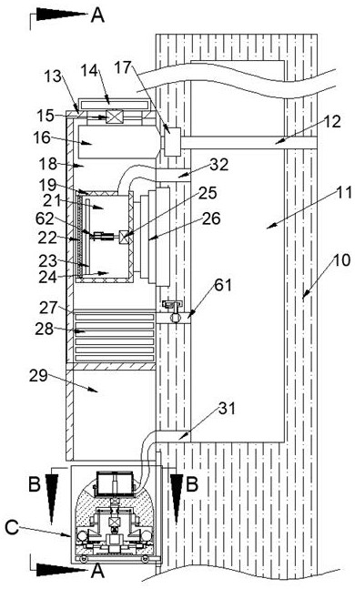
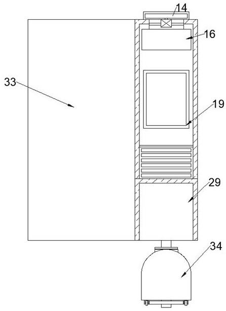
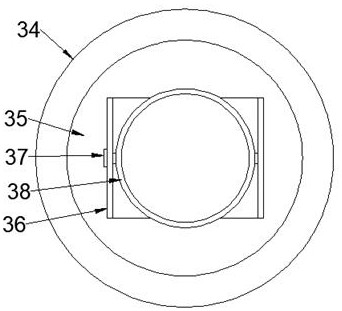
[0018] Combine below Figure 1-5 The present invention is described in detail, wherein, for the convenience of description, the orientations mentioned below are defined as follows: figure 1 The up, down, left, right, front and back directions of the projection relationship itself are the same.

[0019] A corridor emergency fire fighting box equipment described in conjunction with accompanying drawings 1-5 includes a wall 10 and a wall cavity 11 arranged in the wall 10, and a fire hydrant box is fixed on the left side of the wall 10 13. The fire hydrant box 13 is provided with a robot cavity 29, and the left wall of the robot cavity 29 is fixed with a lifting electric slide rail 71, and a supporting plate 72 is slid inside the lifting electric slide rail 71, and the support A robot 34 is arranged on the upper side of the plate 72, and a robot chamber 39 is arranged inside the robot chamber 39, and a first expansion ball 41 is fixed around the robot chamber 39, and a vent pipe ...


PUM


Abstract

The invention discloses a corridor emergency fire disaster fire fighting box device. The corridor emergency fire disaster fire fighting box device comprises a wall body and a wall body cavity formed in the wall body, wherein a fire hydrant box is fixedly arranged on the left side of the wall body; a robot cavity is formed in the fire hydrant box; a lifting electric sliding rail is fixedly arrangedon the left wall of the robot cavity; a supporting plate is arranged in the lifting electric sliding rail in a sliding manner; and a robot is arranged on the upper side of the supporting plate. Afterthe corridor emergency fire disaster fire fighting box device is installed at the designated position, the fire fighting robot can be released, emergency fire fighting or cooling is assisted, the escape time is provided for escape personnel, towels can be provided for people without towels or help, part of smoke can be preferentially discharged out of a building, more escape time is provided forthe escape personnel, and the survival probability during a fire disaster is increased.

Description

technical field [0001] The invention relates to a fire-fighting box device for emergency fires in corridors, and mainly relates to the technical field of emergency fire-fighting. Background technique [0002] The fire hydrant box refers to the box used to store fire hydrants. It is used to extinguish fires when a fire occurs. It must be equipped with water belts and water guns. According to the opening method, press the spring lock on the door, and the pin will automatically exit. After opening the door, remove the water gun and turn the hose reel, pull out the hose, and connect the hose interface with the fire hydrant interface at the same time, pull it out Turn the hand wheel of the indoor fire hydrant in the opening direction of the power switch on the inner wall of the box to spray water to extinguish the fire, but these require trained personnel to operate, and it is impossible to automatically extinguish the fire at the place where the fire spreads or where the heat ga...

Claims


Application Information

Patent Timeline
Patent Type & Authority Applications(China)
IPC IPC(8): A62C35/20A62C27/00A62C31/03A62C37/00A62C99/00A62B7/00F24F7/06
CPCA62B7/00A62C27/00A62C31/03A62C35/20A62C37/00A62C99/0072F24F7/06
Inventor 牛常冷
Owner 象山奋凡消防科技有限公司
Learn More