Bolt device, electric control lock and door
An electronically controlled lock and bolt technology, which is applied to building locks, non-mechanical transmission-operated locks, buildings, etc., can solve problems such as low safety performance, inability to close the lock body, and high power consumption, achieving high safety performance and energy saving Effect of power output and power consumption reduction
- Summary
- Abstract
- Description
- Claims
- Application Information
AI Technical Summary
Problems solved by technology
Method used
Image
Examples
Embodiment 1
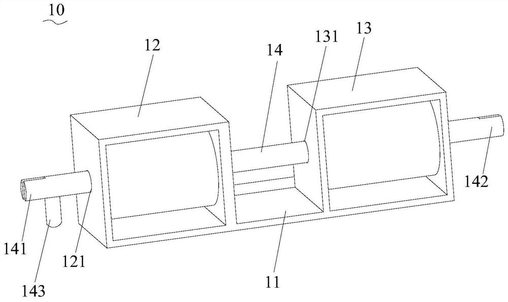
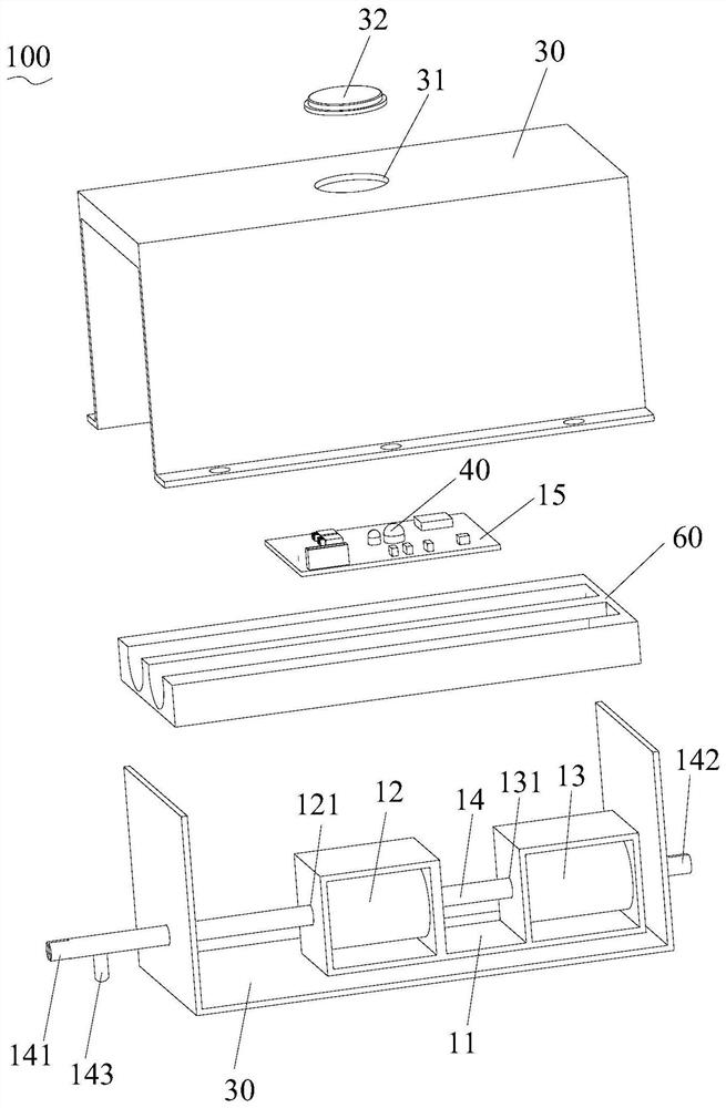
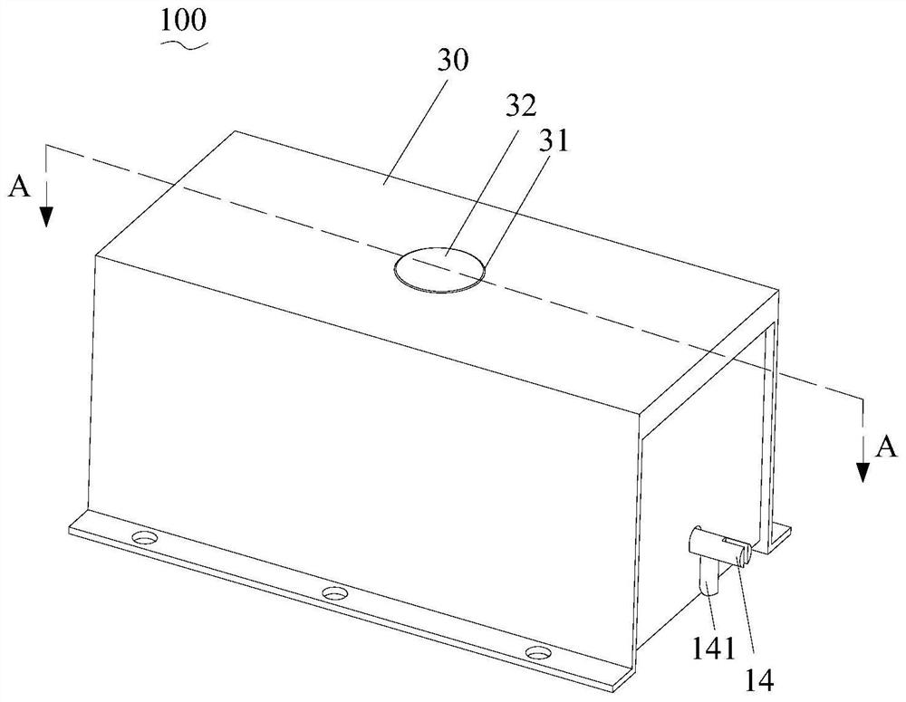
[0034] see Figure 1 to Figure 3 , The latch device 10 of the present invention includes a fixing plate 11 , a first coil 12 , a second coil 13 , a latch 14 and a controller 15 . The first coil 12 and the second coil 13 are fixed on the fixing plate 11 . The first end 141 of the pin 14 passes through the first through hole 121 of the first coil 12 , and the second end 142 passes through the second through hole 131 of the second coil 13 . The controller 15 is used to control the first coil 12 or the second coil 13 to be energized. When the first coil 12 is energized, the pin 14 moves in a first direction, and when the second coil 13 is energized, the pin 14 moves in a second direction.
[0035] In the latch device 10 of the present invention, compared with the opening and closing locks of traditional door locks such as electric control locks and electromagnetic locks, the controller 15 controls the energization of the first coil 12 or the second coil 13 respectively under two ...
Embodiment 2
[0041] Please combine figure 1 , figure 2 and Figure 6 , The electric control lock 100 of the embodiment of the present invention includes a latch device 10 and a locking structure 20 matched with the latch device.
[0042] In the electric control lock 100 of the embodiment of the present invention, compared with the locking of traditional door locks such as electric control locks and electromagnetic locks, the first coil 12 or the second coil 13 is turned on or off under the control of the controller 15 in different situations. When the current is turned on, the first coil 12 or the second coil 13 only consumes electricity at the moment of energization, and generates magnetic force to complete the driving movement of the plug 14 while being energized. When the electric control lock 100 is applied to scenes such as opening and closing doors, access control, etc., it is not necessary to supply power to the electric control lock 100 all the time in order to generate magnetic...
Embodiment 3
[0049] Further, please combine figure 2 and Figure 4 , the electric control lock 100 also includes a switch lock trigger mechanism 40 connected to the controller 15 .
[0050] Specifically, in this embodiment, the switch lock trigger mechanism 40 can receive the switch lock trigger from the outside world, and when receiving the switch lock trigger, it can send an induction signal of unlocking or locking to the controller 15, and the induction signal can be an electrical signal. signal etc. The controller 15 can control the current on and off of the first coil 12 or the second coil 13 according to the induction signal of unlocking or locking, that is, according to different situations, so as to control the movement of the bolt 14, so as to control the unlocking or locking of the electronically controlled lock 100. the goal of.
[0051] Exemplarily, when the controller 15 receives the lock trigger signal of the switch lock trigger mechanism 40, the controller 15 controls th...
PUM
 Abstract
Description
Claims
Application Information
 - R&D
- Intellectual Property
- Life Sciences
- Materials
- Tech Scout
- Unparalleled Data Quality
- Higher Quality Content
- 60% Fewer Hallucinations
Browse by: Latest US Patents, China's latest patents, Technical Efficacy Thesaurus, Application Domain, Technology Topic, Popular Technical Reports.
© 2025 PatSnap. All rights reserved.Legal|Privacy policy|Modern Slavery Act Transparency Statement|Sitemap|About US| Contact US: help@patsnap.com


