Method for producing a decorative surface, in particular of a wood workpiece
A decorative, wood surface technology, applied in the field of equipment for implementing the method, can solve problems such as a large number of manual operations
- Summary
- Abstract
- Description
- Claims
- Application Information
AI Technical Summary
Problems solved by technology
Method used
Image

Examples
no. 1 approach
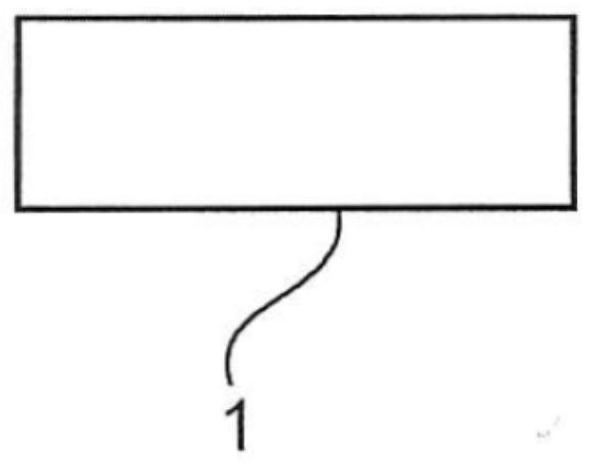
[0054] exist Figure 1a The workpiece 1 is shown in a side view, which is designed here as a plate-shaped workpiece 1 . The workpiece 1 contains solid wood or wood fibers at least in partial regions of the surface.
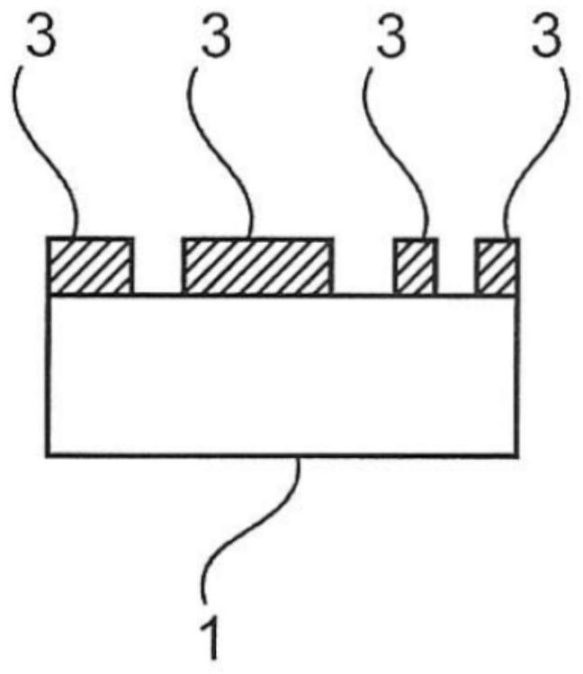
[0055] A covering 3 is applied to the upward facing surface of the workpiece 1 . The covering 3 is applied in such a way that at least some parts of the surface of the workpiece 1 are covered by the covering 3 . The result of this imposition is in Figure 1b shown in . The covering 3 is used for sealing on the surface of the workpiece 1 so that the area of the surface of the workpiece 1 to which the covering 3 is applied is sealed. Thus, the surface is masked for the next step, ie sub-regions of the surface of the workpiece 1 are no longer exposed as before.
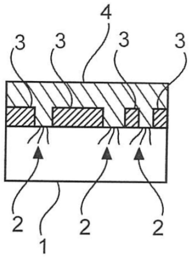
[0056] In a further step, a liquid 4 is applied to the surface of the masked workpiece 1 . The liquid 4 here only comes into contact with exposed (ie uncovered) areas of the surface of the workpiece ...
PUM
 Abstract
Description
Claims
Application Information
PatSnap Eureka turns technology decisions into work you can execute. Powered by our Innovation Knowledge Graph, it runs expert workflows across engineering, life sciences, materials and intellectual property. Get your review-ready output in minutes.


