Cylinder hole honing tool

A technology for honing and cutting tools, applied in the field of honing equipment, can solve the problems of inability to achieve geometric accuracy, precise control, diameter and roundness fluctuations of cylinder holes, ensure product processing quality, reduce tool costs and labor waste, and improve equipment start-up. rate effect

Pending Publication Date: 2021-01-22
SAIC GENERAL MOTORS +2
View PDF0 Cites 0 Cited by
  • Summary
  • Abstract
  • Description
  • Claims
  • Application Information

AI Technical Summary

Problems solved by technology

[0003] Nowadays, the universal joint connecting device with the end of the honing connecting rod that can float is used to assemble and connect with the honing tool, which is used to ensure the uniform and stable force on the surface of the cylinder bore wall during the honing process, and to ensure the geometric accuracy and stability of the cylinder bore after honing is completed. The surface is microscopically accurate, but the tool connected by the floating universal joint connection device is easily affected by factors such as external force or rotation, which will cause the honing tool to swing. When the honing head enters the cylinder hole or during the honing process, the honing head or honing strip hits the top edge of the cylinder hole. (such as: chamfering), the honing head or honing sand bar, bump damage
[0004] Cylinder bore honing is generally done by controlling the number of strokes and honing time of the honing tool to process the required cylinder bore diameter. Due to the different wear conditions of the sand bars, the geometric accuracy of the cylinder bore (including cylindricity , diameter, etc.), there are often fluctuations in dimensions such as diameter and roundness

Method used


Image

  • Cylinder hole honing tool
  • Cylinder hole honing tool
  • Cylinder hole honing tool

Examples


Embodiment Construction

[0035] The present invention will be further described below in conjunction with specific drawings.

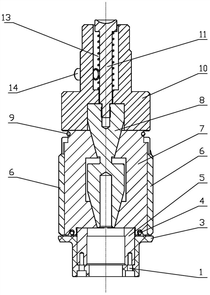
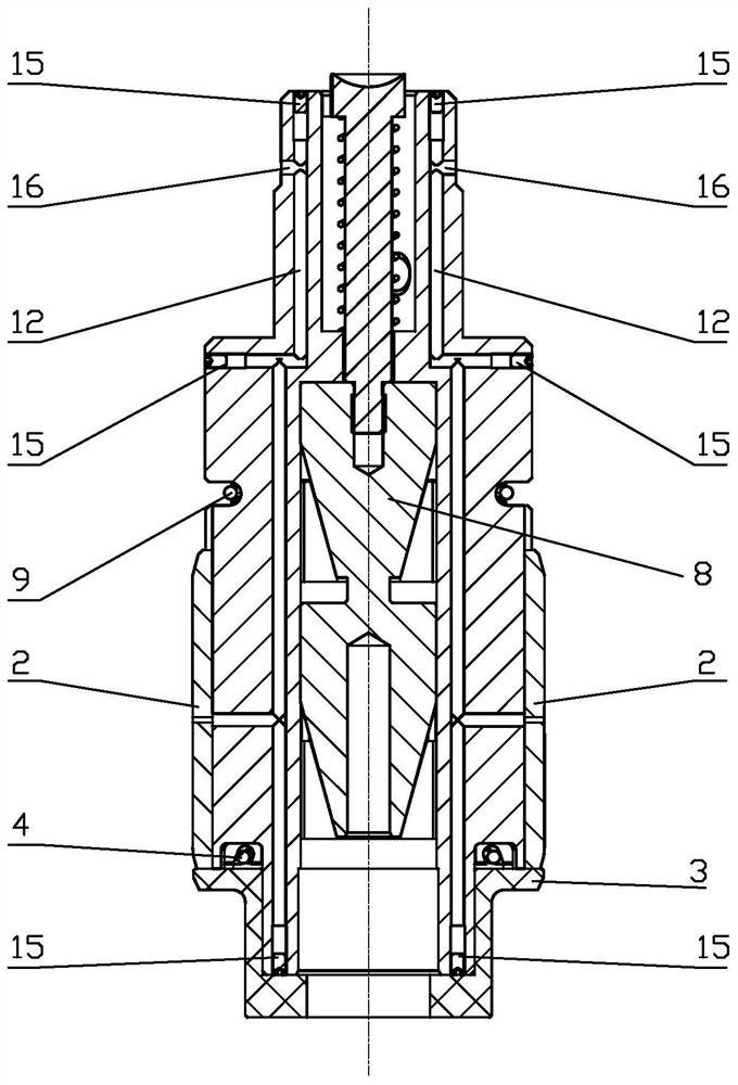
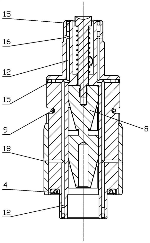
[0036] Such as Figure 5 As shown, the cylinder bore honing tool of the present invention is used for honing the cylinder bore 22 of the engine block 24, and the anti-rotation pin 14 and the locking groove 17 of the honing tool are respectively connected with the anti-rotation pin mounting hole 21 and the locking groove 17 of the connecting rod 19. The locking key cooperates to fix. The present invention specifically includes the head body 10, the sand bar seat 7 and the support body 5 connected in sequence, such as figure 1 As shown, the head body 10 and the sand bar seat 7 are provided with an expanding cone 8, and the sand bar seat 7 is provided with a sand bar 6; Cone 8; expanding knife bar 11 and expanding cone 8 cooperate to drive sand bar seat 7 and sand bar 6 radial knife; expanding knife bar compression spring 13 is combined with expanding knife bar 11, and the driv...


PUM


Abstract

The invention relates to a cylinder hole honing tool comprising a head body, an abrasive strip base and a support body which are connected in sequence; an expansion cone is arranged in the head body and the abrasive strip base, and abrasive strips are arranged on the abrasive strip base; a cutter expansion rod is arranged in the head body, and the lower end of the cutter expansion rod is connectedwith the expansion cone; an upper cutter retracting spring and a lower cutter retracting spring are arranged at the upper and lower ends of the abrasive strip base, so that the abrasive strip base isattached to the expansion cone; a guide alloy strip is arranged on the surface of the abrasive strip base, and chamfers are arranged at the upper and lower ends of the guide alloy strip and the abrasive strips; and anti-collision rings which can be used for blocking and protecting the bottom ends of the guide alloy strip and the abrasive strips are mounted on the support body. According to the cylinder hole honing tool, the problem that the honing abrasive strip, the honing head and the top of the cylinder hole are damaged due to swing of the honing tool is solved properly, and the equipmentstarting rate is increased; the product machining quality is guaranteed, and the tool cost and work waste are reduced; and meanwhile, damage to the honing tool and the abrasive strips is avoided.

Description

technical field [0001] The invention relates to a cylinder bore honing tool, which belongs to the technical field of honing equipment. Background technique [0002] When honing the cylinder bore honing tool, it is necessary to solve the problem that the honing head or the honing abrasive strip hits the top edge of the cylinder bore (such as: chamfering) when the honing head enters the cylinder bore or during the honing process, and the real-time cylinder bore diameter measurement during the precise control process question. [0003] At present, the universal joint connection device with the end of the honing connecting rod that can float is used to assemble and connect with the honing tool, which is used to ensure the uniform and stable force on the surface of the cylinder hole wall during the honing process, and to ensure the geometric accuracy and stability of the cylinder hole after the honing is completed. The surface is microscopically accurate, but the tool connected ...

Claims


Application Information

Patent Timeline
IPC IPC(8): B24B33/02B24B33/08
CPCB24B33/02B24B33/08B24B33/087
Inventor 吕昆仑闵信来李晶君
Owner SAIC GENERAL MOTORS
Why Eureka
Try Eureka