Auxiliary device for new energy automobile part detection

A technology of new energy vehicles and auxiliary devices, which is applied in the direction of workpiece clamping devices, lighting device parts, lighting devices, etc., and can solve the problems of affecting the detection efficiency of auto parts, the staff's strong sense of fatigue, and the inability to adjust the height of parts, etc. problem, to achieve good fixing effect, avoid movement, and facilitate the effect of picking and placing tools

Inactive Publication Date: 2021-01-22
SUZHOU TRACEABILITY STANDARD CERTIFICATION & INSPECTION CO LTD
View PDF10 Cites 4 Cited by
  • Summary
  • Abstract
  • Description
  • Claims
  • Application Information

AI Technical Summary

Problems solved by technology

[0002] New energy vehicles refer to the use of unconventional vehicle fuels as the power source, comprehensive vehicle power control and advanced technology in driving, and the formation of vehicles with advanced technical principles, new technologies and new structures. In today's social development, New energy vehicles have developed rapidly. In the production process of new energy vehicles, the components need to be tested after the production is completed. During the detection, a detection table is often used for auxiliary clamping to fix the components, which is convenient For the detection of staff, the parts in the currently used testing platform are fixed in a fixed position, and the height of the parts cannot be adjusted. During the long-term use of staff of different heights, improper height will lead to a strong sense of fatigue for the staff , prone to fatigue, affecting the detection efficiency of auto parts

Method used


Image

  • Auxiliary device for new energy automobile part detection
  • Auxiliary device for new energy automobile part detection
  • Auxiliary device for new energy automobile part detection

Examples


Embodiment Construction

[0025] The following will clearly and completely describe the technical solutions in the embodiments of the present invention with reference to the accompanying drawings in the embodiments of the present invention. Obviously, the described embodiments are only some, not all, embodiments of the present invention. Based on the embodiments of the present invention, all other embodiments obtained by persons of ordinary skill in the art without making creative efforts belong to the protection scope of the present invention.

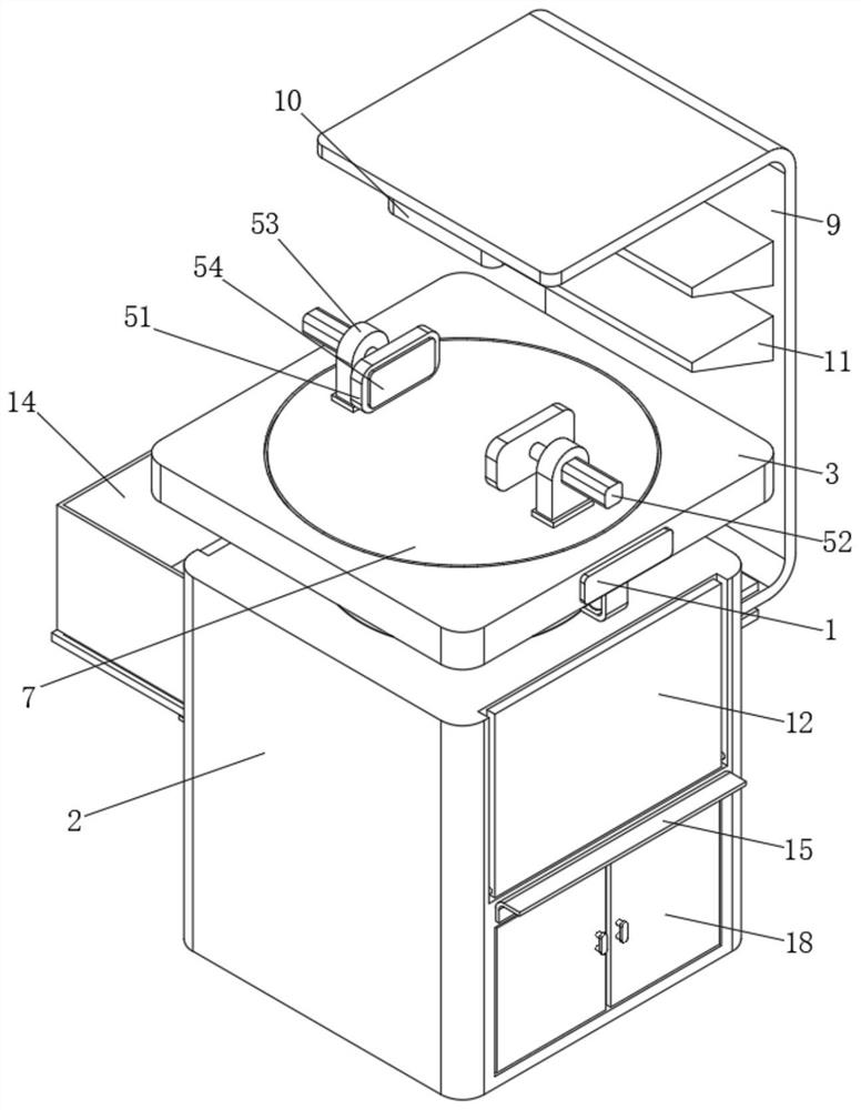
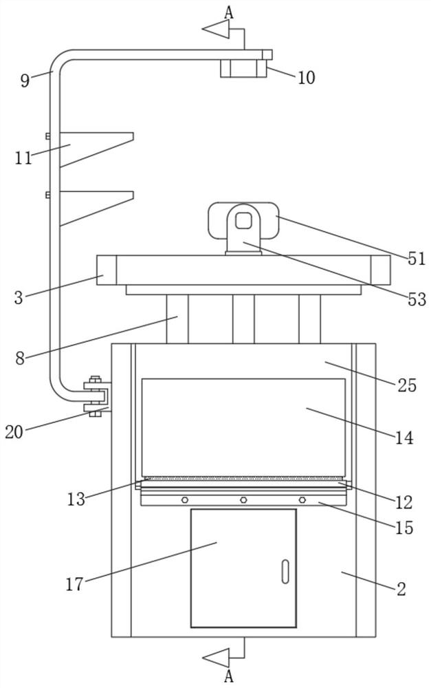
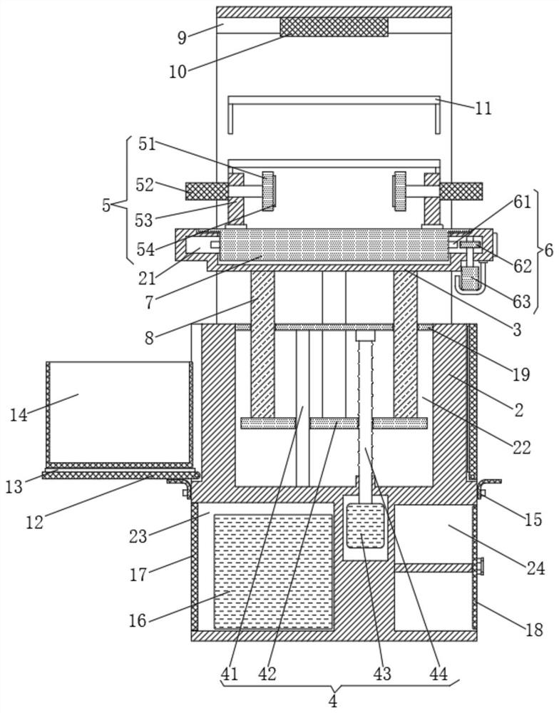
[0026] see Figure 1-3 , the present invention provides a technical solution: a new energy vehicle parts detection auxiliary device, including a box 2, a lifting mechanism 4 and a parts fixing mechanism 5;

[0027] Box 2: It is a square prism box. The inside of the box body 2 is provided with a lifting chamber 22, a power supply room 23 and a tool room 24. The lifting chamber 22 is located at the top of the power supply room 23. The top is fixed with a top pl...


PUM


Abstract

The invention discloses an auxiliary device for new energy automobile part detection. The auxiliary device for new energy automobile part detection comprises a box body, a lifting mechanism and a partfixing mechanism, wherein the box body is a regular-quadrangular-prism box, a lifting cavity, a power supply chamber and a tool chamber are formed in the box body, the lifting cavity is located at the top end of the power supply chamber and formed in the top end of the box body, a top plate is fixed to the top end of the lifting cavity through bolts, the power supply chamber is located at the left side of the tool chamber, a power supply is installed in the power supply chamber, a first box door is formed in the left side surface of the power supply chamber, and a second box door is formed inthe right side surface of the tool chamber; and the lifting mechanism comprises a guide rod, a lifting plate, a first servo motor and a lead screw, the end part of the guide rod and the end part of the lead screw are both installed at the bottom end of the top plate. The auxiliary device for new energy automobile part detection can automatically and accurately adjust the height of a detection table, so that the part detection efficiency can be increased, and the fatigue feeling of workers can be reduced.

Description

technical field [0001] The invention relates to the technical field of auto parts detection auxiliary devices, in particular to a new energy auto parts detection auxiliary device. Background technique [0002] New energy vehicles refer to the use of unconventional vehicle fuels as the power source, comprehensive vehicle power control and advanced technology in driving, and the formation of vehicles with advanced technical principles, new technologies and new structures. In today's social development, New energy vehicles have developed rapidly. In the production process of new energy vehicles, the components need to be tested after the production is completed. During the detection, a detection table is often used for auxiliary clamping to fix the components, which is convenient For the detection of staff, the parts in the currently used testing platform are fixed in a fixed position, and the height of the parts cannot be adjusted. During the long-term use of staff of differen...

Claims


Application Information

Patent Timeline
IPC IPC(8): B25H1/16B25H1/14B25H1/12B25B11/00F21V33/00
CPCB25B11/00B25H1/12B25H1/14B25H1/16F21V33/00
Inventor 张菡莉
Owner SUZHOU TRACEABILITY STANDARD CERTIFICATION & INSPECTION CO LTD
Why Eureka
Try Eureka