An emergency floating device for an underwater robot

An underwater robot and emergency technology, applied in the directions of underwater ships, underwater operation equipment, motor vehicles, etc., can solve the problems of small volume, reduced floating speed, and increased gravity of the underwater robot itself, so as to facilitate recycling and processing, speed up Ascension speed, the effect of improving the ability to face special situations

Active Publication Date: 2021-05-25
HARBIN ENG UNIV
View PDF0 Cites 0 Cited by
  • Summary
  • Abstract
  • Description
  • Claims
  • Application Information

AI Technical Summary

Problems solved by technology

[0004] The purpose of the present invention is to solve the problem that the existing underwater robot has a small volume, and the feasibility of the floating device needs the assistance of other devices to complete the function, which leads to the increase of the gravity of the underwater robot and the decrease of the floating speed, and then provides an underwater robot. emergency flotation device

Method used


Image

  • An emergency floating device for an underwater robot
  • An emergency floating device for an underwater robot
  • An emergency floating device for an underwater robot

Examples


specific Embodiment approach 1

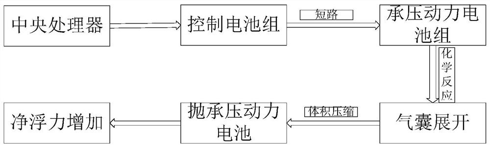
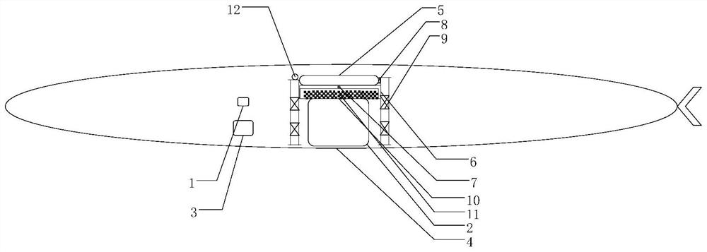
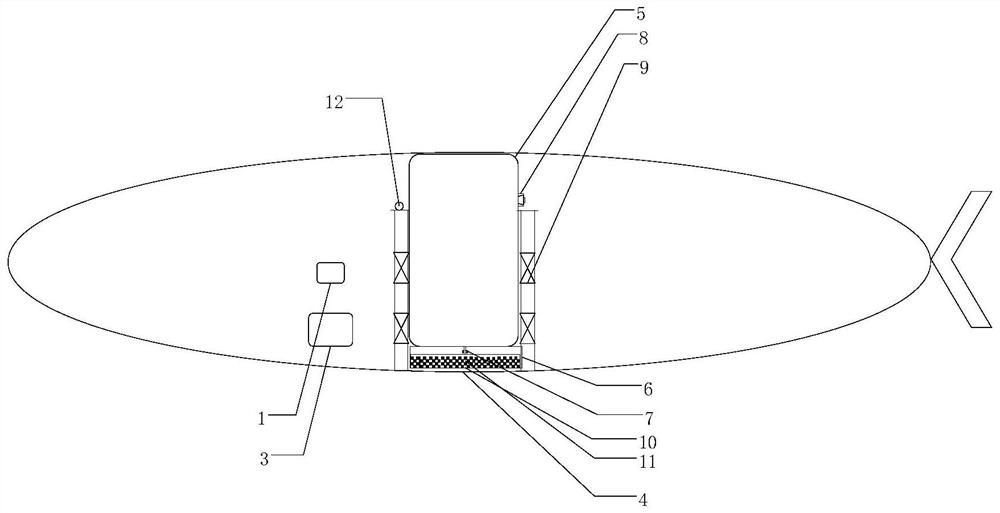
[0022] Specific implementation mode one: combine Figure 2 to Figure 5 Describe this embodiment, an underwater robot emergency flotation device of this embodiment, the underwater robot emergency flotation device includes a central processing unit 1, a pressure-bearing power battery pack 2, an elastic shell hatch 4, an air bag 5, a watertight Chemical reaction chamber 6, inflation valve 7, deflation valve 8, gas separator 10, ammonium dichromate 11 and two guides 9, the central processing unit 1 is coupled to the embedded control computer of the underwater robot, and the watertight chemical reaction The cabin 6, the pressurized power battery pack 2 and the elastic shell hatch 4 are arranged from top to bottom on the center of gravity line of the underwater robot, the pressurized power battery pack 2 is connected to the central processing unit 1 through wires, and the two guides 9 Vertically opposite to the shell of the underwater robot on both sides of the watertight chemical r...

specific Embodiment approach 2

[0024] Specific implementation mode two: combination figure 2 , image 3 with Figure 5 To describe this embodiment, the watertight chemical reaction chamber 6 of this embodiment is located at the center of the center of gravity of the underwater robot. Other compositions and connections are the same as in the first embodiment.

specific Embodiment approach 3

[0025] Specific implementation mode three: combination Figure 2 to Figure 4 Describe this embodiment, the elastic housing door 4 of this embodiment is located at the bottom of the center of gravity line. Other compositions and connections are the same as those in Embodiment 1 or Embodiment 2.


PUM


Abstract

The utility model relates to an emergency floating device for an underwater robot, which relates to the field of marine technical equipment. The invention solves the problem that the existing underwater robot has a small volume, and the function feasibility of the floating device requires the assistance of other devices, which leads to the increase of the underwater robot's own gravity and the decrease of the floating speed. The watertight chemical reaction chamber, the pressurized power battery pack and the elastic shell hatch of the present invention are arranged from top to bottom on the center of gravity line of the underwater robot, and the two guides are arranged vertically opposite to each other on both sides of the watertight chemical reaction chamber. The two sides of the chemical reaction chamber are respectively connected with two guides. The gas separator is wrapped with ammonium dichromate and placed inside the watertight chemical reaction chamber. The airbag is embedded on the top of the watertight chemical reaction chamber. The bottom of the airbag is connected to the gas separator through an inflatable tube. , the inflation tube is provided with an inflation valve. The invention is used to optimize the ratio of the functionality of the internal device of the underwater robot to the occupied volume, and increase the net buoyancy of the underwater robot.

Description

technical field [0001] The invention relates to the field of marine technical equipment, in particular to an emergency floating device for an underwater robot. Background technique [0002] Due to the unknown and complexity of the underwater environment, the underwater robot will face various failures of incapacity, so that emergency floating means should be adopted to avoid more serious consequences. The current floating means are mainly divided into two aspects: (1) reducing the gravity of the underwater robot itself. Such as discarding disposable ballast, removing the ballast water in the ballast water tank: (2) increasing the displacement volume of the underwater robot to increase the buoyancy. Such as deploying air bags or oil bags in underwater robots. And these two kinds of devices all need other devices to guarantee the feasibility of its function, and this has just increased difficulty to the narrow and small underwater robot of volume originally. In addition, in...

Claims


Application Information

Patent Timeline
Patent Type & Authority Patents(China)
IPC IPC(8): B63G8/24B63C11/52
CPCB63C11/52B63G8/24
Inventor 李岳明闫力新庞家明曹建张国成
Owner HARBIN ENG UNIV
Why Eureka
Try Eureka