
Through-flow type integrated wind wheel structure for warm air blower

A cross-flow heater technology, which is applied to mechanical equipment, gasification materials, non-variable pumps, etc., can solve the problems of inconvenient maintenance and replacement of blades, the single use of heaters for heating, and high economic costs, and achieve light volume Quantification, good aromatherapy effect, guaranteed installation effect

Active Publication Date: 2019-04-16
琦品家居(浙江)股份有限公司
View PDF8 Cites 0 Cited by
  • Summary
  • Abstract
  • Description
  • Claims
  • Application Information

AI Technical Summary

Problems solved by technology

[0003] At present, some heaters are made of metal materials, so their weight is relatively heavy. Most of the blades and end plates of the cross-flow wind rotor are fixedly connected. If the blades are damaged, the entire cross-flow wind rotor needs to be replaced. , it is inconvenient to repair and replace the blades, the economic cost is high, and most of the common heaters are used for single heating, and their functionality is poor. For the current leisure and health lifestyle, ordinary heaters cannot meet people’s needs. To solve the above problems, therefore, design a kind of cross-flow integrated wind wheel structure of the heater

Method used


Image

  • Through-flow type integrated wind wheel structure for warm air blower
  • Through-flow type integrated wind wheel structure for warm air blower
  • Through-flow type integrated wind wheel structure for warm air blower

Examples


Embodiment Construction

[0024] The following will clearly and completely describe the technical solutions in the embodiments of the present invention with reference to the accompanying drawings in the embodiments of the present invention. Obviously, the described embodiments are only some, not all, embodiments of the present invention. Based on the embodiments of the present invention, all other embodiments obtained by persons of ordinary skill in the art without making creative efforts belong to the protection scope of the present invention.

[0025] In the description of the present invention, it should be noted that the orientation or positional relationship indicated by the terms "vertical", "upper", "lower", "horizontal" etc. is based on the orientation or positional relationship shown in the drawings, and is only In order to facilitate the description of the present invention and simplify the description, it does not indicate or imply that the device or element referred to must have a specific o...


PUM


Abstract

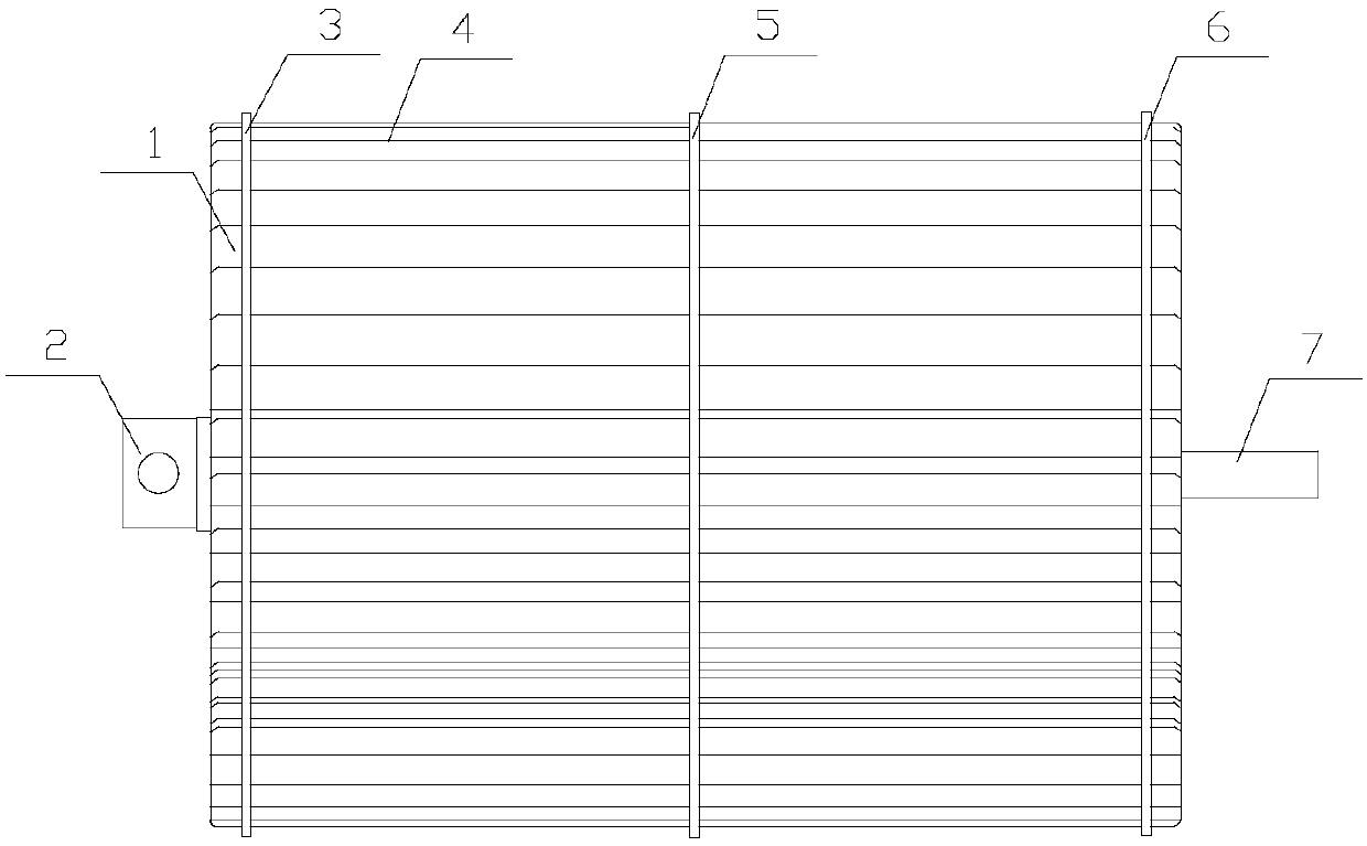
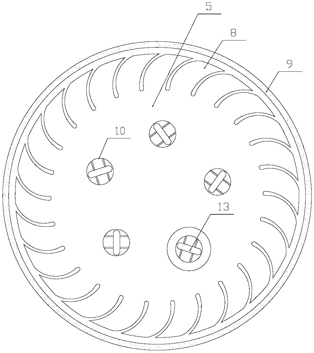
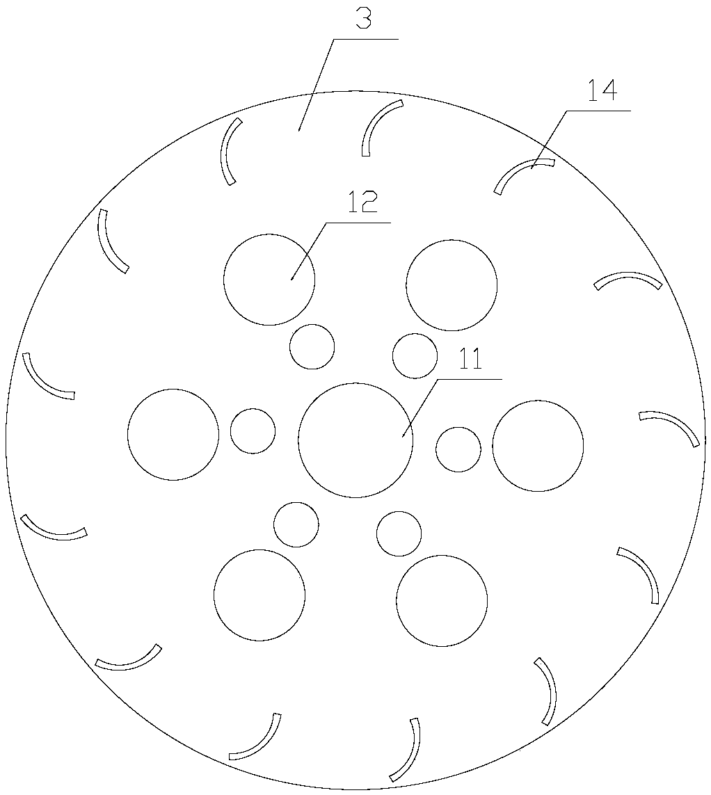
The invention discloses a through-flow type integrated wind wheel structure for a warm air blower. The structure comprises a wind wheel body, a coupler and a rotating shaft. The wind wheel body comprises a first end plate, a second end plate, middle partition plates and a plurality of blades. Center holes are formed in the center position of the first end plate and the center position of the second end plate. The coupler is inserted into the center hole of the first end plate. The rotating shaft is inserted into the center hole of the second end plate. A plurality of blade installing holes areuniformly formed in the outer periphery of the first end plate and the outer periphery of the second end plate. The middle partition plates comprise an inner partition plate and an outer partition plate. A plurality of through holes are formed in the middle portion of the inner partition plate at intervals. A plurality of installing clamping grooves are uniformly formed in the outer edge of the inner partition plate at intervals. The size of the inner partition plate is smaller than that of the outer partition plate. The inner partition plate is arranged in the outer partition plate. Threadsare arranged on the outer wall of the inner partition plate and the inner wall of the outer partition plate. The inner partition plate and the outer partition plate are in thread connection. By arranging a capsule aromatherapy box, when the warm air blower is started, heating is carried out to heat aromatherapy sheets to be volatilized, under rotating of the wind wheel body, fragrance of the aromatherapy sheets is blown out to the outer space, and thus the whole environment is full of fragrance.

Description

technical field [0001] The invention relates to the technical field of a wind wheel of a heater, in particular to a through-flow integrated wind wheel structure of a heater. Background technique [0002] The heater is a combined unit composed of a fan, an electric motor and an air heater. It is suitable for various types of workshops, and can be used for circulating air heating when the air does not contain dust and flammable or explosive gases. The heater can be used independently for heating, and is generally used to supplement the insufficient part of the radiator or use the radiator as on-duty heating, and the remaining heat load is borne by the heater. Because of its simple structure, small size, stable airflow, high dynamic pressure coefficient, long reach distance and low noise, the heater is widely used in people's daily life. Heaters can be roughly divided into centrifugal type, tubular flow type and axial flow type according to the different forms of wind wheel a...

Claims


Application Information

Patent Timeline
Patent Type & Authority Applications(China)
IPC IPC(8): F04D29/30F04D29/62F04D25/08A61L9/03
CPCA61L9/032F04D25/08F04D29/30F04D29/624
Inventor 张时勇
Owner 琦品家居(浙江)股份有限公司
Learn More