Overwater Floating bridge and erection method

A floating bridge and floating board technology, applied in the direction of floating bridges, bridge construction, bridges, etc., can solve the problems of long-term use, troublesome operation, etc., and achieve the effects of convenient operation and installation, low water absorption and simple structure

Active Publication Date: 2019-05-21
重庆高新技术产业研究院有限责任公司
View PDF6 Cites 0 Cited by
  • Summary
  • Abstract
  • Description
  • Claims
  • Application Information

AI Technical Summary

Problems solved by technology

[0003] The technical problem to be solved by the present invention is to provide a floating bridge on water and its erection method, which can solve the problems of troublesome operation and long-term use.

Method used


Image

  • Overwater Floating bridge and erection method
  • Overwater Floating bridge and erection method
  • Overwater Floating bridge and erection method

Examples


Embodiment 1

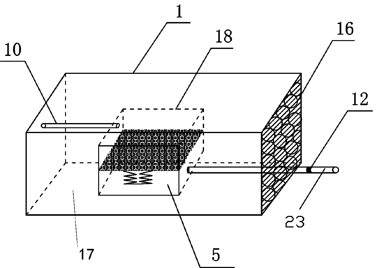
[0044] Such as Figure 2-Figure 2 As shown, a floating board unit includes a ceramsite board 1. The ceramsite board 1 includes a plate body frame 17 made of a flexible mesh body. The plate body frame 17 is filled with a filling body composed of N layers of ceramsite 16 and lightweight concrete. , N≥1;

[0045] A groove 18 is provided in the ceramsite board 1, and a water storage lifting device 5 is placed in the groove;

[0046] The outer surface of each side of the board frame 17 is provided with an inclusion 3, the inclusion 3 is wrapped with an outer mesh body 14, and the space between the outer mesh body 14 and the inclusion 3 is filled with lightweight concrete.

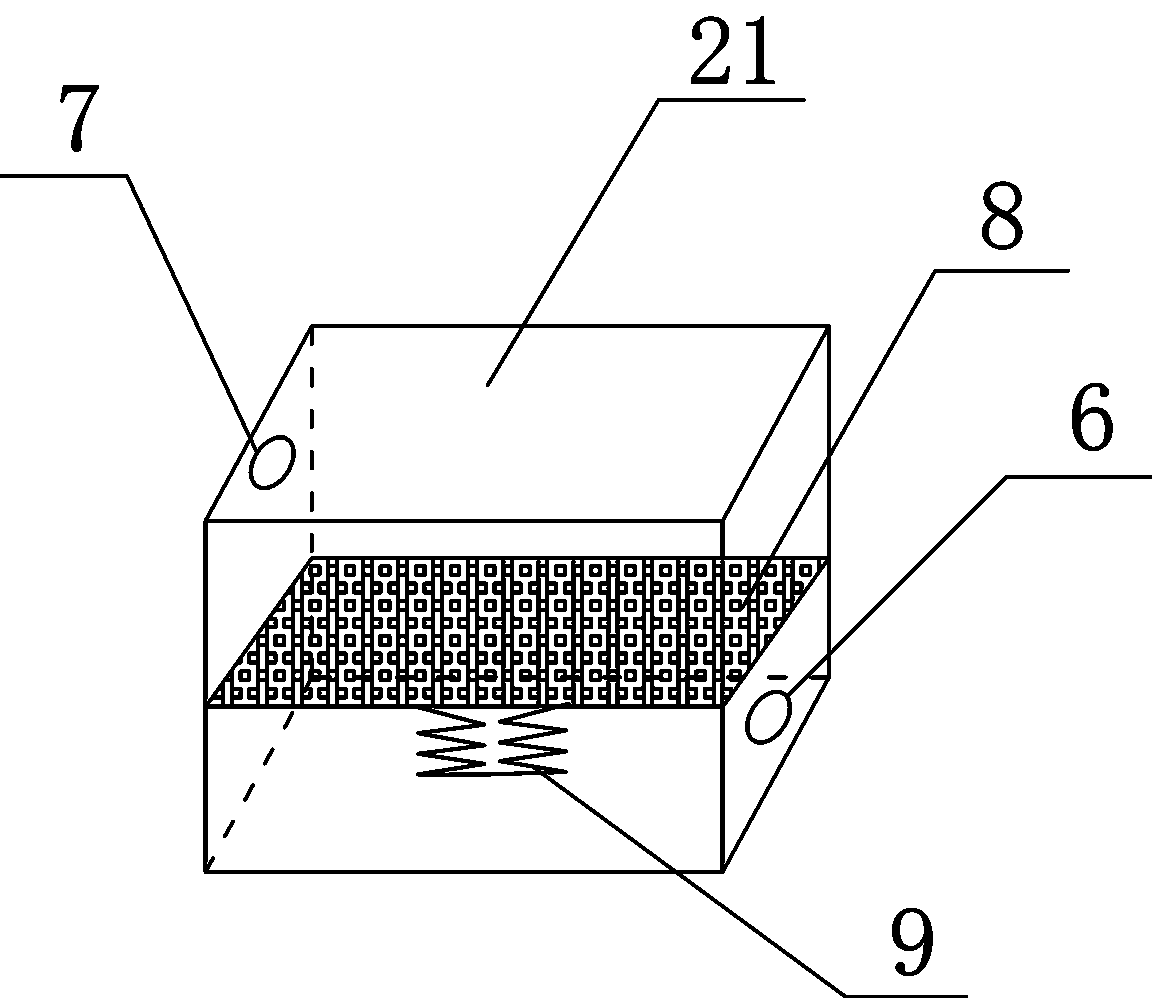
[0047] The water storage lifting device 5 includes a hollow closed container body 21. The internal space of the closed container body 21 is divided into a water outlet space and a water inlet space by a piston 8. The piston 8 and the bottom surface of the closed container body 21 are connected by a lifter 9, and the in...

Embodiment 2

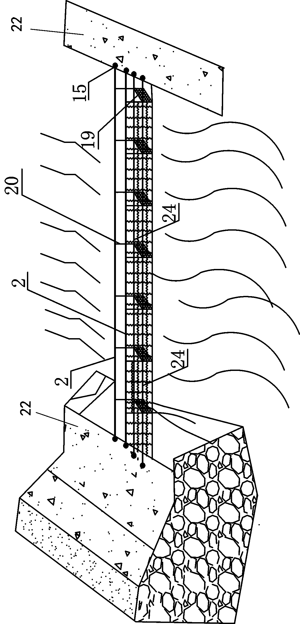
[0050] Such as figure 1 , Figure 4-Figure 6 As shown, a floating bridge is provided with two rows of steel cables 2 on the foundation 22 of the two river banks. It is characterized in that: multiple floating board units 19 are connected to the steel cables 2 through suspension cables 20 and spliced ​​to form a whole floating bridge ;

[0051] The steel cable 2 is set on the foundation 22 on the banks of the two rivers through an anchor 15.

[0052] The four top corners of the floating board unit 19 are respectively installed with shackles 4, one end of the suspension cable 20 is fixed on the shackle 4 of the floating board unit 19, and the other end of the suspension cable 20 is fixedly connected with the steel cable 2. Each floating board unit A double-layer flexible net 11 is arranged between the two suspension cables 20 on the same side.

[0053] The two adjacent floating board units 19 are connected by a hook.

[0054] The ceramsite 16 adopts shale ceramsite, fly ash ceramsite,...

Embodiment 3

[0057] Such as figure 1 , Figure 4-Figure 6 As shown, a method for erecting the above-mentioned floating pontoon includes the following steps:

[0058] Step 1: Manufacturing floating plate unit 19:

[0059] Step 1-1: Manufacturing the ceramsite board 1: Place the water storage lifting device 5 in the middle of the ceramsite board structure model, and connect the PVC pipes to the water inlet 6 and the water outlet 7 of the water storage lifting device 5 respectively The inlet pipe 23 and the outlet pipe 10 are formed; a layer of flexible mesh is laid on the bottom of the ceramsite plate structure model, and N layers of ceramsite 16 are laid on the flexible mesh body, N≥1, and another layer is arranged on the N layer of ceramsite 16 Layer flexible nets, and use iron wires to sew the two flexible nets together to form a plate frame 17, wrap the water storage lifting device 5 in the middle of the plate frame 17, and then pour lightweight concrete into the plate frame 17, , The ceram...


PUM


Abstract

The invention relates to a floating plate unit, which comprises a ceramsite plate, wherein the ceramsite plate comprises a plate body frame made of a flexible mesh body, N layers of filling bodies consisting of ceramsite and light concrete are filled in the plate body frame, and N is more than or equal to 1; a groove is formed in the ceramsite plate, and a water storage lifting device is arrangedin the groove; a wrapping body is arranged on the outer surface of each side surface of the plate body frame, an outer net body is wrapped outside the wrapping body, and light concrete is filled in the space between the outer net body and the wrapping body. The invention relates to an overwater floating bridge manufactured by adopting the floating plate units. Two rows of steel cables are arrangedon the foundation of two riverbank shores, and a plurality of floating plate units are hung on the steel cables through suspension cables and spliced to form an integral floating bridge. The overwater floating bridge and the erection method can solve the problems that the operation is troublesome, the height cannot be automatically adjusted and the water floating bridge cannot be used for a longtime; the overwater floating bridge has the advantages that the structure is simple, the operation is convenient, the buoyancy of the floating bridge is adjustable, the bridge deck can be automatically adjusted along with the flood season and the dry season of the river, and the feasibility is good.

Description

Technical field [0001] The invention relates to the technical field of bridge bodies, in particular to a floating bridge on water and an erection method. Background technique [0002] At present, the main types of floating floating bridges include temporary floating bridges, inflatable floating bridges, folding motorized floating bridges, and telescopic floating bridges. The inflatable pontoon is mainly formed by connecting the inflatable floating body through the connecting components. When in use, it is quickly inflated by an electric inflatable pump or a compressed gas cylinder. The inflated section is connected to the other section, and it continues to extend to the opposite bank as the inflation. The telescopic pontoon and the folding motorized pontoon are mainly composed of The support frame and the bridge deck are composed of a telescopic drive device connected to the support frame, which can be expanded when needed and contracted when not in use. Inflatable floating brid...

Claims


Application Information

Patent Timeline
Patent Type & Authority Applications(China)
IPC IPC(8): E01D15/14E01D19/12
Inventor 刘杰高素芳兰俊莫承林谢晓康韩绍康高进张罗送孙涛黎照唐洪宇李洪亚罗越文姜锋
Owner 重庆高新技术产业研究院有限责任公司
Why Eureka
Try Eureka